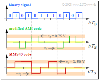
Two different ternary transmission codes are used with ISDN, which are to be clarified in the diagram at an exemplary binary input signal.
The upper diagram shows twelve bits $($each with bit duration $T_{\rm B})$.
- On the $\rm S_{0}$ interface $($between NTBA and terminal equipment$)$, the $\text{modified AMI code}$ is used. The difference to the conventional AMI code is the swapping $0 \Leftrightarrow 1$ of the binary input signal.
- In contrast, the $\text{MMS43 code}$ $($Modified Monitoring Sum 4B3T$)$ is used on the $\rm U_{K0}$ interface, where four binary symbols are replaced by three ternary symbols $($voltage values $0 \ {\rm V}, +2.5 \ {\rm V}$ and $-2.5 \ {\rm V})$. The assignment is done depending on the previously coded symbols.
Notes:
- The exercise belongs to the chapter "ISDN Basic Access".
- Information on the MMS43 code can be found in the chapter "Block Coding with 4B3T Codes" of the book "Digital Signal Transmission".
- Information on the AMI code can be found in the chapter "Symbolwise Coding with Pseudo-Ternary Codes" of the same book.
Questions
Solution
(1) The first two statements are correct:
- The modified AMI code is a pseudo-ternary code with $T_{\rm S} = T_{\rm B}$ and symbol-wise coding. The stated assignments apply to the conventional AMI code.
- On the other hand, in the modified AMI code the binary "1" is represented by the voltage value $0 \ \rm V$ and the binary "0" alternately by $+s_{0}$ resp. $-s_{0}$, where for $s_{0} = 0.75 \ \rm V$ is to be set.
(2) The equivalent bit rate of the AMI encoded signal is $R_{\rm C} = {\rm log_2}\hspace{0.05cm}(3)/T_{\rm S}$.
- The bit rate of the redundancy-free binary source signal is equal to $R_{\rm B} = 1/T_{\rm B}$.
- With $T_{\rm S} = T_{\rm B}$, according to the chapter "Basics of Coded Transmission" of the book "Digital Signal Transmission", we obtain for the (relative) redundancy of the modified AMI code:
- $$r_{\rm AMI} = \frac{R_{\rm C}-R_{\rm B}}{R_{\rm C}} = 1 - \frac{1}{{\rm ld}\,(3)} \hspace{0.15cm}\underline{\approx 36.9\,\%} \hspace{0.05cm}.$$
(3) Using the unit impedance $R = 1 \ \rm \Omega $, the following applies to the transmit power $($with the unit $\rm V^{2})$:
- $$P_{\rm S,\,AMI} = {1}/{2} \cdot {s_0}^2 = {1}/{2} \cdot {0.75\,{\rm V}}^2 \approx 0.28\,{\rm V^2} \hspace{0.05cm}.$$
- Here it is considered that the AMI encoded signal is equal to $0 \ \rm V$ in half of the time.
- Finally, considering the impedance $R = 100 \ \rm \Omega$, we get:
- $$P_{\rm S,\,AMI} = \frac{0.28\,{\rm V^2}}{100\,\Omega} \hspace{0.15cm}\underline{ = 2.8\,{\rm mW}} \hspace{0.05cm}.$$
(4) The MMS43 code actually operates in blocks, with $m_{q} = 4$ binary symbols replaced by $m_{c} = 3 $ ternary symbols:
- $$4 \cdot T_{\rm B} = 3 \cdot T_{\rm S}\hspace{0.3cm}\Rightarrow \hspace{0.3cm} T_{\rm S} = {4}/{3} \cdot T_{\rm B} \hspace{0.05cm}.$$
- That means: The first solution does not apply as well as the last one. Only solution 2 is correct:
- In block coding, the binary symbol "0" cannot be uniformly replaced by the same code symbol. Rather, the encoding can be described as follows, assuming the running digital sum ${\it \Sigma}_{0} = 0$ at the beginning $($see graphic in the information section$)$:
- $$\mathbf{0 1 0 1} \hspace{0.1cm} \ \Rightarrow \ \hspace{0.1cm}\mathbf{0 + +}\hspace{0.2cm}({\it \Sigma}_1 = 2)\hspace{0.05cm},$$
- $$ \mathbf{0 1 1 1} \hspace{0.1cm} \ \Rightarrow \ \hspace{0.1cm}\mathbf{- \,0 \,\,+}\hspace{0.2cm}({\it \Sigma}_2 = 2)\hspace{0.05cm},$$
- $$ \mathbf{0 1 0 1} \hspace{0.1cm} \ \Rightarrow \ \hspace{0.1cm}\mathbf{- \,0\,\,\, 0}\hspace{0.2cm}({\it \Sigma}_3 = 1) \hspace{0.05cm}.$$
- "Exercise 1.4Z" discusses the MMS43 code in more detail.
(5) The MMS43 code belongs to the class of 4B3T codes. For these it is valid:
- $$R_{\rm B} = \frac{1}{T_{\rm B}}, \hspace{0.2cm} R_{\rm C} = \frac{{\rm ld}\,(3)}{T_{\rm S}}\hspace{0.3cm} \Rightarrow \hspace{0.3cm}r_{\rm MMS43} = 1 - \frac{R_{\rm B}}{R_{\rm C}} = 1 - \frac{T_{\rm S}/T_{\rm B}}{{\rm ld}\,(3)} = 1 - \frac{4/3}{{\rm log_2}\,(3)} \hspace{0.15cm}\underline{\approx 15.9\,\%} \hspace{0.05cm}.$$
(6) The following number of ternary symbols are transmitted on the $\rm U_{K0}$ bus per millisecond:
- Channel B1: $64$ binary symbols ⇒ $48$ ternary symbols,
- Channel B2: $64$ binary symbols ⇒ $48$ ternary symbols,
- D channel: $16$ binary symbols ⇒ $12$ ternary symbols,
- Synchronization and control symbols ⇒ $12$ ternary symbols.
As a sum, this results in $120$ ternary symbols per millisecond or $\underline{120,000}$ ternary symbols per second.
(7) Considering the note in the information section and the larger transmission amplitude $s_{0} = 2.5 \ \rm V$ compared to the (modified) AMI code, we obtain:
- $$P_{\rm S,\,MMS43} = \frac{2}{3} \cdot \frac{{s_0}^2}{R} = \frac{2}{3} \cdot \frac{({2.5\,{\rm V}})^2}{100\,{\rm \Omega}} \hspace{0.15cm}\underline{\approx 4.2\,{\rm mW}} \hspace{0.05cm}.$$
