Difference between revisions of "Aufgaben:Exercise 3.6Z: Transition Diagram at 3 States"
| Line 1: | Line 1: | ||
| − | {{quiz-Header|Buchseite= | + | {{quiz-Header|Buchseite=Channel_Coding/Code_Description_with_State_and_Trellis_Diagram}} |
| − | [[File:P_ID2667__KC_Z_3_6.png|right|frame| | + | [[File:P_ID2667__KC_Z_3_6.png|right|frame|State transition diagram for $m = 3$ (incomplete)]] |
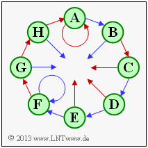
| − | + | In the state transition diagram of an encoder with memory $m$ there are $2^m$ states. Therefore, the diagram shown with eight states describes a convolutional encoder with memory $m = 3$. | |
| − | + | Usually the states are denoted by $S_0, \ \text{...} \ , \ S_{\mu}, \ \text{...} \ , \ S_7$, where the index $\mu$ is determined from the occupancy of the shift register (contents from left to right: $u_{i-1}, u_{i-2}, u_{i-3})$ : | |
:$$\mu = \sum_{l = 1}^{m} \hspace{0.1cm}2\hspace{0.03cm}^{l-1} \cdot u_{i-l} | :$$\mu = \sum_{l = 1}^{m} \hspace{0.1cm}2\hspace{0.03cm}^{l-1} \cdot u_{i-l} | ||
\hspace{0.05cm}.$$ | \hspace{0.05cm}.$$ | ||
| − | + | The state $S_0$ therefore results for the shift register content "$000$", the state $S_1$ for "$100$" and the state $S_7$ for "$111$". | |
| − | + | However, in the above graphic, for the states $S_0, \, \text{...} \, , \, S_7$ placeholder names $\mathbf{A}, \, \text{...} \, , \, \mathbf{H}$ used. In the subtasks '''(1)''' and '''(2)''' you should clarify which placeholder stands for which state. | |
| − | + | For convolutional encoders of rate $1/n$, which will be exclusively considered here, two arrows depart from each state $S_{\mu}$ , | |
| − | * | + | *one red one for the current information bit $u_i = 0$ and. |
| − | * | + | *a blue one for $u_i = 1$. |
| − | + | This is another reason why the state transition diagram shown is not complete. It is to be mentioned furthermore: | |
| − | * | + | * At each state also two arrows arrive, whereby these can be absolutely of the same color. |
| − | * | + | * Next to the arrows there are usually the $n$ code bits. This was also omitted here. |
| Line 28: | Line 28: | ||
| − | + | Hints: | |
| − | * | + | * The exercise belongs to the chapter [[Channel_Coding/Code_Description_with_State_and_Trellis_Diagram| "Code Description with State and Trellis Diagram"]]. |
| − | * In [[Aufgaben: | + | *In [[Aufgaben:Exercise_3.7Z:_Which_Code_is_Catastrophic%3F| "Exercise 3.7Z"]] two convolutional codes with memory $m = 3$ are examined, both of which can be described by the transition diagram analyzed here. |
| − | * | + | *Please include the appropriate ''index'' $\mu$ for all questions. |
| − | * | + | *Reference is made in particular to the sections |
| − | **[[Channel_Coding/ | + | **[[Channel_Coding/Code_Description_with_State_and_Trellis_Diagram#State_definition_for_a_memory_register|"State definition for a memory register"]] as well as. |
| − | ** [[Channel_Coding/ | + | ** [[Channel_Coding/Code_Description_with_State_and_Trellis_Diagram#Representation_in_the_state_transition_diagram|"Representation in the state transition diagram"]]. |
| − | === | + | |
| + | ===Questions=== | ||
<quiz display=simple> | <quiz display=simple> | ||
{Für welche Zustände $S_{\mu}$ stehen die Platzhalter $\mathbf{A}$ und $\mathbf{F}$? | {Für welche Zustände $S_{\mu}$ stehen die Platzhalter $\mathbf{A}$ und $\mathbf{F}$? | ||
Revision as of 15:40, 3 October 2022
In the state transition diagram of an encoder with memory $m$ there are $2^m$ states. Therefore, the diagram shown with eight states describes a convolutional encoder with memory $m = 3$.
Usually the states are denoted by $S_0, \ \text{...} \ , \ S_{\mu}, \ \text{...} \ , \ S_7$, where the index $\mu$ is determined from the occupancy of the shift register (contents from left to right: $u_{i-1}, u_{i-2}, u_{i-3})$ :
- $$\mu = \sum_{l = 1}^{m} \hspace{0.1cm}2\hspace{0.03cm}^{l-1} \cdot u_{i-l} \hspace{0.05cm}.$$
The state $S_0$ therefore results for the shift register content "$000$", the state $S_1$ for "$100$" and the state $S_7$ for "$111$".
However, in the above graphic, for the states $S_0, \, \text{...} \, , \, S_7$ placeholder names $\mathbf{A}, \, \text{...} \, , \, \mathbf{H}$ used. In the subtasks (1) and (2) you should clarify which placeholder stands for which state.
For convolutional encoders of rate $1/n$, which will be exclusively considered here, two arrows depart from each state $S_{\mu}$ ,
- one red one for the current information bit $u_i = 0$ and.
- a blue one for $u_i = 1$.
This is another reason why the state transition diagram shown is not complete. It is to be mentioned furthermore:
- At each state also two arrows arrive, whereby these can be absolutely of the same color.
- Next to the arrows there are usually the $n$ code bits. This was also omitted here.
Hints:
- The exercise belongs to the chapter "Code Description with State and Trellis Diagram".
- In "Exercise 3.7Z" two convolutional codes with memory $m = 3$ are examined, both of which can be described by the transition diagram analyzed here.
- Please include the appropriate index $\mu$ for all questions.
- Reference is made in particular to the sections
Questions
Musterlösung
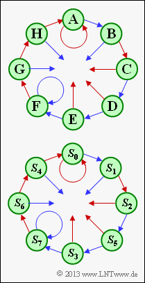
(1) Der Platzhalter $\mathbf{A}$ steht für den Zustand $S_0$ ⇒ $u_{i-1} = 0, \ u_{i-2} = 0, \ u_{i-3} = 0$.
- Dies ist der einzige Zustand $S_{\mu}$, bei dem man durch das Infobit $u_i = 0$ (roter Pfeil) im gleichen Zustand $S_{\mu}$ bleibt.
- Vom Zustand $S_7$ ⇒ $u_{i-1} = 1, \ u_{i-2} = 1, \ u_{i-3} = 1$ kommt man mit $u_i = 1$ (blauer Pfeil) auch wieder zum Zustand $S_7$.
- Einzugeben waren also für $\mathbf{A}$ der Index $\underline{\mu = 0}$ und für $\mathbf{F}$ der Index $\underline{\mu = 7}$.
(2) Ausgehend vom Zustand $\mathbf{A} = S_0$ kommt man entsprechend der Ausgangsgrafik im Uhrzeigersinn mit den roten Pfeilen $(u_i = 0)$ bzw. den blauen Pfeilen $(u_i = 1)$ zu folgenden Zuständen:
- $$u_{i–3} = 0, \ u_{i–2} = 0, \ u_{i–1} = 0, \ u_i = 1 ⇒ s_{i+1} = \mathbf{B} = S_1,$$
- $$u_{i–3} = 0, \ u_{i–2} = 0, \ u_{i–1} = 1, \ u_i = 0 ⇒ s_{i+1} = \mathbf{C} = S_2,$$
- $$u_{i–3} = 0, \ u_{i–2} = 1, \ u_{i–1} = 0, \ u_i = 1 ⇒ s_{i+1} = \mathbf{D} = S_5,$$
- $$u_{i–3} = 1, \ u_{i–2} = 0, \ u_{i–1} = 1, \ u_i = 1 ⇒ s_{i+1} = \mathbf{E} = S_3,$$
- $$u_{i–3} = 0, \ u_{i–2} = 1, \ u_{i–1} = 1, \ u_i = 1 ⇒ s_{i+1} = \mathbf{F} = S_7,$$
- $$u_{i–3} = 1, \ u_{i–2} = 1, \ u_{i–1} = 1, \ u_i = 0 ⇒ s_{i+1} = \mathbf{G} = S_6,$$
- $$u_{i–3} = 1, \ u_{i–2} = 1, \ u_{i–1} = 0, \ u_i = 0 ⇒ s_{i+1} = \mathbf{H} = S_4,$$
- $$u_{i–3} = 1, \ u_{i–2} = 0, \ u_{i–1} = 0, \ u_i = 0 ⇒ s_{i+1} = \mathbf{A} = S_0.$$
- Einzugeben sind also die Indizes $\mu$ in der Reihenfolge 1, 2, 5, 3, 6, 4.
- Die Grafik zeigt den Zusammenhang zwischen den Platzhaltern und den Zuständen $S_{\mu}$.
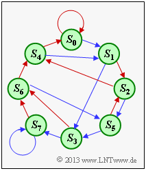
(3) Vom Zustand $S_1$ ⇒ $u_{i–1} = 1, \ u_{i–2} = 0, \ u_{i–3} = 0$ kommt man mit $u_i = 0$ (roter Pfeil) zum Zustand $S_2$. Dagegen landet man mit $u_i = 1$ (blauer Pfeil) beim Zustand $S_3$ ⇒ $u_{i–1} = 1, \ u_{i–2} = 1, \ u_{i–3} = 0$.
Nebenstehende Grafik zeigt das Zustandsübergangsdiagramm mit allen Übergängen. Aus diesem kann abgelesen werden:
- Vom Zustand $S_3$ kommt man mit $u_i = 0$ zum Zustand $S_6$.
- Vom Zustand $S_5$ kommt man mit $u_i = 0$ zum Zustand $S_2$.
- Vom Zustand $S_7$ kommt man mit $u_i = 0$ zum Zustand $S_6$.
Einzugeben sind also die Indizes in der Reihenfolge 3, 6, 2, 6.


