Difference between revisions of "Channel Coding/Error Correction According to Reed-Solomon Coding"
| Line 201: | Line 201: | ||
However, we do not know how many symbols were corrupted $(0 < r ≤ n)$ nor can we name the positions of the error locations $(e_i ≠ 0)$ in the error vector $\underline{c}$ .<br> | However, we do not know how many symbols were corrupted $(0 < r ≤ n)$ nor can we name the positions of the error locations $(e_i ≠ 0)$ in the error vector $\underline{c}$ .<br> | ||
| − | Einen Lösungsansatz für diese Aufgabe bietet das so genannte <i>Error Locator Polynom</i>, das von [https:// | + | Einen Lösungsansatz für diese Aufgabe bietet das so genannte <i>Error Locator Polynom</i>, das von [https://en.wikipedia.org/wiki/W._Wesley_Peterson William Wesley Peterson] eingeführt wurde ⇒ siehe [Pet60]<ref name =''Pet60>Peterson, W.W: ''Encoding and Error-correction Procedures for the Bose-Chaudhuri codes.'' IRE Transactions on Information Theory , IT-6:459{470), 1960.</ref>. Im Deutschen ist hierfür auch der Begriff "Schlüsselgleichung" üblich.<br> |
{{BlaueBox|TEXT= | {{BlaueBox|TEXT= | ||
Revision as of 01:11, 6 September 2022
Contents
- 1 Block diagram and requirements for RS error correction
- 2 Possible code word estimators for RS decoding
- 3 Bounded Distance Decoding Procedure
- 4 Step (A): Evaluation of the syndrome in BDD
- 5 Error Locator Polynomial - Definition and Properties
- 6 Step (B): Set up/evaluate the ELP coefficient vector
- 7 Step (C): Localization of the error locations
- 8 Step (D): Final error correction
- 9 Fast Reed-Solomon decoding
- 10 Exercises for the chapter
- 11 Quellenverzeichnis
Block diagram and requirements for RS error correction
As in the chapter "Decoding at the Erasure Channel" we consider a transmission system with Reed–Solomon coding characterized by the two code parameters $n=2^m-1$ and $k$ . With the generator matrix $\boldsymbol{\rm G}$ the relation between the information word $\underline {u}$ and the codeword $\underline {c}$ is:
- \[\underline {c} = {\rm enc}(\underline {u}) = \underline {u} \cdot { \boldsymbol{\rm G}} \hspace{0.3cm} {\rm mit} \hspace{0.3cm}\underline {u} = (u_0, u_1, \hspace{0.05cm}\text{...} \hspace{0.05cm}, u_i, \hspace{0.05cm}\text{...} \hspace{0.05cm}, u_{k-1})\hspace{0.05cm}, \hspace{0.2cm} \underline {c} = (c_0, c_1, \hspace{0.05cm}\text{...} \hspace{0.05cm}, c_i, \hspace{0.05cm}\text{...} \hspace{0.05cm}, c_{n-1}) \hspace{0.05cm}.\]
The information symbols $u_i$ and also the code symbols $C_i$ originate from the field ${\rm GF}(q)$ with $q=n+1=2^m$; they are representable by $m$ binary symbols (bits).
A comparison of this block diagram with the corresponding "Block diagram for RS fault detection" shows:
- The main difference is in the discrete channel model used (highlighted in green). Instead of the cancellation channel ("$m$ BEC") now the $m$ BSC is considered. For each bit of the code symbol $c_i$ the Binary Symmetric Channel (BSC) is applied. A bit error with respect to the $i$ bit results in $y_i \ne c_i$.
- In the "last chapter" uncertain bits were already marked by erasures $\rm E$. The exercise of the code word finder $\rm (CWF)$ was to reconstruct the decoding result $\underline {y}$ from the garbled received words $\underline {z}$ .
- If the number $e$ of extinctions is smaller than the minimum distance $d_{\rm min}$, this succeeds and we get $\underline {z} = \underline {c}$. Otherwise, the codeword finder reports that it cannot decode the current received word $\underline {y}$ . A wrong decision $(\underline {z} \ne \underline {c})$ was excluded at the BEC.
- In this chapter, the first decoder block is now referred to as code word estimator $\rm (CWS)$. The naming is to make clear that due to the $m$ BSC model, wrong decisions $(\underline {z} \ne \underline {c})$ are inevitable, namely when multiple symbol errors distort the received word $\underline {y}$ to a valid codeword.
$\text{Conclusion:}$
- The decoder's exercise is to determine its output vector $\underline {v}$ so that it matches the information word $\underline {u}$ "as well as possible". More precisely formulated:
- \[{ \rm Pr(Block\hspace{0.15cm}error)} = { \rm Pr}( \underline{v} \ne \underline{u}) \stackrel{!}{=} { \rm Minimum}\hspace{0.05cm}.\]
- Because of deterministic mapping $\underline{c} = {\rm enc}(\underline{u})$ and $\underline{v} = {\rm enc}^{-1}(\underline{z})$ holds in the same way:
- \[{ \rm Pr(Block\hspace{0.15cm}error)} = { \rm Pr}( \underline{z} \ne \underline{c}) \stackrel{!}{=} { \rm Minimum}\hspace{0.05cm}.\]
The two blocks highlighted in yellow are not considered further below. The focus of the considerations is now the code word estimator $\rm (CWS)$ highlighted in red.
Possible code word estimators for RS decoding
The right sketch of the following graphic illustrates the task again, where here the channel model "$m$ BSC" is replaced by the additive error vector' $\underline{e} = \underline{y} - \underline{c}$ . The sketch on the left illustrates the relationship between these three vectors.
This task is to be clarified by an example.
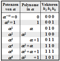
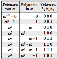
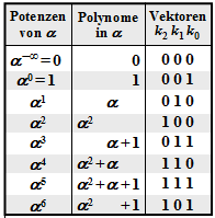
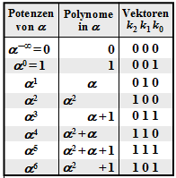
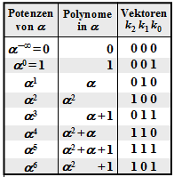
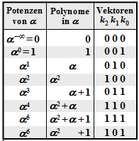
$\text{Example 1:}$ Let all symbols be elements of $\rm GF(2^3) \in \{0, 1, \alpha^1, \alpha^2, \alpha^3, \alpha^4, \alpha^5, \alpha^6\}$. For conversion
- between the coefficient representation $($with the order $k_2$, $k_1$, $k_0)$
- and the exponent representation $($as powers of the primitive element $\alpha)$
the adjacent table can be used.
In this example, the codeword and received words are in coefficient notation:
- \[\underline{c} = \Big ( (010), (001), (100),(010),(100),(111),(111)\Big )\hspace{0.05cm},\]
- \[\underline{y} =\Big ( (011), (001), (000),(010),(100),(111),(111)\Big )\hspace{0.05cm}.\]
This results in the following for the error vector $\underline{e} = \underline{y} - \underline{c}$:
- \[\underline{e} \hspace{0.05cm} = \hspace{0.05cm} \Big ( (001), (000), (100), (000),(000),(000),(000)\Big )\hspace{0.05cm}.\]
Converted to the exponential representation, we get:
- \[\underline{c} = \Big ( \alpha^1, \hspace{0.09cm}1\hspace{0.09cm}, \alpha^2,\alpha^1,\alpha^2,\alpha^5,\alpha^5\Big )\hspace{0.05cm},\]
- \[\underline{y} =\Big ( \alpha^3, \hspace{0.09cm}1\hspace{0.09cm}, \hspace{0.09cm}0\hspace{0.09cm},\alpha^1,\alpha^2,\alpha^5,\alpha^5\Big )\hspace{0.05cm},\]
- \[\underline{e} = \Big ( \hspace{0.09cm}1\hspace{0.09cm}, \hspace{0.09cm}0\hspace{0.09cm}, \hspace{0.05cm}\alpha^2,\hspace{0.12cm}0\hspace{0.12cm},\hspace{0.12cm}0\hspace{0.12cm},\hspace{0.12cm}0\hspace{0.12cm},\hspace{0.12cm}0\hspace{0.12cm}\Big )\hspace{0.05cm}.\]
The task of the code word estimator $\rm (CWS)$ is to find the most probable code word to $\underline{y}$ and to pass its result $\underline{z} = \underline{c}_i$ to the following mapping. There are several ways to do this:
- Hard Decision Maximum Likelihood Decoding $\text{(HD MLD)}$,
- Bounded Distance Decoding $\text{(BDD)}$,
- Decoding over half the minimum distance.
These decoding principles are described below.
Hard Decision Maximum Likelihood Decoding $\text{(HD MLD)}$:
One chooses from all possible Reed–Solomon codewords $\underline{c}_i$ $($hierof there are in total $q^k)$ the one with the least "Hamming distance" to the received word $\underline{y}$ from. Thus the result is:
- \[\underline{z} = {\rm arg} \min_{\underline{c}_{\hspace{0.03cm}i} \hspace{0.05cm} \in \hspace{0.05cm} \mathcal{C}_{\rm RS}} \hspace{0.1cm} d_{\rm H}(\underline{y} \hspace{0.05cm}, \hspace{0.1cm}\underline{c}_{\hspace{0.03cm}i})\hspace{0.05cm}.\]
The decision here happens on the maximum inference probability ${\rm Pr}(\underline{c}_i\hspace{0.05cm}|\hspace{0.05cm}\underline{y})$ and leads to the best possible result. For more details see "ML Decision at the BSC Channel". A decision is always made even if the number $r$ of symbol errors is larger than the correction capability $t$ of the code. However, in such a case the decoding result is very uncertain.
- It should be mentioned again that maximum likelihood decoding always decides.
- Decoding failure is impossible.
- But of course there are also wrong decisions.
Bounded Distance Decoding $\text{(BDD)}$:
If the number $r$ of symbol errors in the received words $\underline{y}$ is not greater than the correction capability $t = ⌊(d_{\rm min}- 1)/2⌋$ of the code, one can correct the $r$ symbol errors completely. However, it is also true:
- The case $r > t$ leads to an abort of the decoding process with no result. In other words:
- Only those received words towards the center of the sphere are decoded, which lie in a sphere around it with radius $t$ .
- Other received words are marked as undecodable, for example as erasure.
Decoding over half the minimum distance:
Here also in the case $r > t$ an attempt is made to decode the codeword. In contrast to $\text{HD MLD}$, which also decodes beyond half the minimum distance, a decoding failure is not per se excluded here, however.
For the remainder of this chapter, we will deal exclusively with Bounded Distance Decoding. The reason for this is the enormous complexity of Maximum Likelihood Decoding proportional to $q^{n-k}$.
Bounded Distance Decoding Procedure
In the following, the individual steps of the BDD algorithm are described briefly and in a recipe-like manner. On the following pages, the individual points will be dealt with in more detail and the procedure will be illustrated using typical examples.
$\rm (A)$ $\text{Calculation and evaluation of syndrome}$ ⇒ "Detailed description"
- Calculate from the received word $\underline{y}$ and the parity-check matrix $\boldsymbol{\rm H }$ of the code the syndrome $\underline {s} = \underline {y} \cdot \boldsymbol{\rm H }^{\rm T}$.
- If $\underline {s} =\underline {0}$, set the BDD output $\underline {z} =\underline {y}$ and terminate the decoding process for that received word.
- Otherwise set the parameter $r = 1$ and continue with step $\rm (B)$ .
$\rm (B)$ $\text{Determine the actual symbol error count } r$ ⇒ "Detailed description"
- Create and check the equations $\underline {\it \Lambda} _l \cdot\underline {s}^{\rm T} = 0$ for $l = 1,$ ... , $2 \cdot t -r$ assuming that the received word contains exactly $r$ symbol errors.
- $\underline {\it \Lambda} _l $ denotes the generalized $\text{ELP}$ coefficient vectors, where "$\text{ELP}$" stands for "Error Locator Polynomial" and $t$ denotes the correctability of the code.
For the Reed–Solomon codes, uniformly $t = ⌊(n-k)/2 ⌋$.
- If there is a unique solution, then continue with step $\rm (C)$ . In the received vector $\underline{y}$ there are then indeed exactly $r$ symbols corrupted and in the error vector $\underline{e}$ there are $r$ entries not equal to $0$.
- Otherwise increase $r$ by $1$. If $r ≤ t$, then repeat step $\rm (B)$ from the beginning: The previously assumed $r$ was obviously too small. Therefore now a new attempt with larger $r$.
- If the new $r$ is greater than the correction capability $t$ of the code, the current received word cannot be decoded. End the decoding attempt with an error message.
$\rm (C)$ $\text{Localization of the }r \text{ error locations}$ ⇒ "Detailed description"
- Create the error locator polynomial ${\it \Lambda}(x)$ and find its $r$ zeros in ${\rm GF}(q) \hspace{-0.05cm}\setminus \hspace{-0.05cm} \{0\}$.
- An error at location $i$ is present whenever ${\it \Lambda}(\alpha^{i}) = 0$ .
$\rm (D)$ $\text{Determination of }r \text{ error values and correction}$ ⇒ "Detailed description"
- Now the $r$ error locations are known. Replacing in the received vector $\underline{y}$ the wrong symbols with erasures ⇒ $y_i = \rm E$, if $e_i ≠ 0$, we find the result $\underline{y}$ corresponding to the chapter "Reed-Solomon Decoding at the Erasure Channel".
- An alternative: From the equation $\underline {e} \cdot \boldsymbol{\rm H }^{\rm T} = \underline {s}$ one arrives at a linear system of equations for the faulty symbols $(e_i = 0)$ taking advantage of the error-free sites $(e_i \ne 0)$.
Step (A): Evaluation of the syndrome in BDD
As shown in section "Principle of Syndrome Decoding" syndrome $\underline{s}$ can be used to decode a linear code.
With the received word $\underline{y}$ equal to codeword $\underline{c}$ plus error vector $\underline{e}$ applies:
- \[\underline {s} = \underline {y} \cdot { \boldsymbol{\rm H }}^{\rm T}= \underline {c} \cdot { \boldsymbol{\rm H }}^{\rm T}+ \underline {e} \cdot { \boldsymbol{\rm H }}^{\rm T} \hspace{0.05cm}.\]
Since always $\underline {c} \cdot { \boldsymbol{\rm H }}^{\rm T} =\underline {0}$ holds, it follows from $\underline{s}= \underline{0}$ also $\underline {e} \cdot { \boldsymbol{\rm H }}^{\rm T} =\underline{0}$. That is:
- With very high probability, from $\underline{s}= \underline{0}$ it is also possible to infer $\underline{e}= \underline{0}$ and thus also the correct decoding result $\underline{z}= \underline{y}$ . The decoding process would be finished.
- But there are also error patterns $\underline{e} \ne \underline{0}$ that lead to the syndrome $\underline{s}= \underline{0}$ . Such patterns certainly contain more than $t$ symbol errors, so here too it makes sense to abort the decoding process. All subsequent calculations would also not lead to success.
$\text{Example 2:}$ This and the following examples on the next pages are always based on the Reed–Solomon code $\text{RSC (7, 3, 5)}_8$ so that the conversions given in the graph in $\rm GF(2^3)$ can be used. The received words are:
- \[\underline{y}=\big (\alpha^3,\hspace{0.05cm} 1,\hspace{0.05cm} 0, \hspace{0.05cm}\alpha^1, \hspace{0.05cm} \alpha^2, \hspace{0.05cm} \alpha^5, \hspace{0.05cm} \alpha^5 \big).\]
With the "Parity-Check Matrix" $\boldsymbol{\rm H }$ results for the syndrome:
- \[\underline {s} = \underline {y} \cdot { \boldsymbol{\rm H } }^{\rm T}= \begin{pmatrix} \alpha^3, \hspace{0.05cm}1, \hspace{0.05cm}0, \hspace{0.05cm}\alpha^1, \hspace{0.05cm}\alpha^2, \hspace{0.05cm}\alpha^5, \hspace{0.05cm}\alpha^5 \end{pmatrix}\cdot \begin{pmatrix} 1 & 1 & 1 & 1 \\ \alpha^1 & \alpha^2 & \alpha^3 & \alpha^4 \\ \alpha^2 & \alpha^4 & \alpha^6 & \alpha^1 \\ \alpha^3 & \alpha^6 & \alpha^2 & \alpha^5 \\ \alpha^4 & \alpha^1 & \alpha^5 & \alpha^2 \\ \alpha^5 & \alpha^3 & \alpha^1 & \alpha^6 \\ \alpha^6 & \alpha^5 & \alpha^4 & \alpha^3 \end{pmatrix}. \]
These vector–matrix multiplications gives the result:
- \[\underline {s} \hspace{-0.05cm} = \hspace{-0.05cm} (\alpha^3 , \alpha^3 , \alpha^3 , \alpha^3) + (\alpha^1 , \alpha^2 , \alpha^3 , \alpha^4) + (0,0,0,0) \hspace{-0.05cm}+\hspace{-0.05cm} (\alpha^4,1,\alpha^3,\alpha^6)+(\alpha^6,\alpha^3,1,\alpha^4)\hspace{-0.05cm}+\hspace{-0.05cm}(\alpha^3,\alpha^1,\alpha^6,\alpha^4) \hspace{-0.05cm}+\hspace{-0.05cm} (\alpha^4,\alpha^3,\alpha^2,\alpha^1)\]
- \[\Rightarrow \hspace{0.3cm} \underline {s} = \text{...} \hspace{0.05cm}= (\alpha^5,\alpha^2,\alpha^3,\alpha^1) \hspace{0.05cm}.\]
So the received word was corrupted. Otherwise it should have resulted in $\underline{e}= \underline{0} = (0, 0, 0, 0)$ .
The description of the decoding process at $\text{RSC (7, 3, 5)}_8$ is continued in "$\text{Example 4}$"
Error Locator Polynomial - Definition and Properties
After the syndrome calculation in step $\rm (A)$ with the result $\underline{s} \ne \underline{0}$ we know,
- that the received word $\underline{y}$ does not match the codeword $\underline{c}$ respectively
- that the error vector $\underline{e} = (e_0, \hspace{0.05cm}e_1, \hspace{0.05cm}\text{ ...}\hspace{0.05cm} , e_{n-1})$ certainly includes elements not equal to $0$ .
However, we do not know how many symbols were corrupted $(0 < r ≤ n)$ nor can we name the positions of the error locations $(e_i ≠ 0)$ in the error vector $\underline{c}$ .
Einen Lösungsansatz für diese Aufgabe bietet das so genannte Error Locator Polynom, das von William Wesley Peterson eingeführt wurde ⇒ siehe [Pet60]Cite error: Invalid <ref> tag;
invalid names, e.g. too many. Im Deutschen ist hierfür auch der Begriff "Schlüsselgleichung" üblich.
$\text{Definition:}$ Es sei bekannt, dass genau $r$ Elemente des Fehlervektors $\underline{e}$ ungleich Null sind, erkennbar am Hamming–Gewicht $w_{\rm H}(\underline{e}) = r$.
- Ebenfalls bekannt sei die Menge ${I}_{\rm FP}$ der Fehlerpositionen:
- \[I_{\rm FP} = \{ i \hspace{0.1cm}\vert \hspace{0.1cm} e_i \ne 0,\hspace{0.1cm} 0 \le i < n \}\hspace{0.05cm}.\]
- Dann gilt für das Error Locator Polynom $\rm (ELP)$:
- \[{\it \Lambda}(x)=x \cdot \prod_{i\hspace{0.05cm}\in \hspace{0.05cm} I_{\rm FP} }(x-\alpha^i) =x \cdot \big [{\it \lambda}_0 + \lambda_1 \cdot x+\ldots+{\it \lambda}_{r-1} \cdot x^{r-1}+x^r \big ].\]
Vom Error Locator Polynom wissen wir aufgrund der Definition:
- Wegen des Faktors $x$ vor dem Produktzeichen ist ${\it \Lambda}(x= 0) = 0$.
- Weitere $r$ Nullstellen ergeben sich für $x = \alpha^{i}$ mit $i \in I_{\rm FP}$, das heißt, für alle Fehlerpositionen.
- Dagegen ergibt das Error Locator Polynom für $i ∉ I_{\rm FP}$ ⇒ $e_i = 0$ keine Nullstelle: ${\it \Lambda}(x= \alpha^{i}) \ne0$.
Wir suchen also die $r$ nichttrivialen Nullstellen von ${\it \Lambda}(x)$ mit dem Argument $x ∈ {\rm GF}(q) \hspace{-0.05cm}\setminus \hspace{-0.05cm} \{0\}$. Gelingt uns dies, so kennen wir die $r$ Fehlerpositionen, jedoch noch nicht die tatsächlichen Fehlerwerte $e_i ∈ {\rm GF}(q)$.
$\text{Beispiel 3:}$
Es gelte $n=7$ ⇒ $q=8$, $r=2$ und $I_{\rm FP} = \{2, \hspace{0.05cm}4\}$: ![]()
Damit erhält man für das Error Locator Poynom aus ${\rm GF}(2^3)$:
- \[{\it \Lambda}(x)=x \cdot (x\hspace{-0.05cm}-\hspace{-0.05cm}\alpha^2) \cdot (x\hspace{-0.05cm}-\hspace{-0.05cm}\alpha^4)= x \cdot (x\hspace{-0.05cm}+\hspace{-0.05cm}\alpha^2) \cdot (x\hspace{-0.05cm}+\hspace{-0.05cm}\alpha^4) =x \cdot \big [x^2 \hspace{-0.05cm}+ \hspace{-0.05cm}(\alpha^2 + \alpha^4) \cdot x + \alpha^6\big ] \]
- \[\Rightarrow \hspace{0.3cm} {\it \Lambda}(x)= x \cdot \big [\alpha^6 + \alpha \cdot x + x^2\big ]\hspace{0.05cm}.\]
Die weiteren Nullstellen $($außer bei $x = 0)$ ergeben sich hier natürlich für $x = \alpha^2$ und $x = \alpha^4$, wie eine Kontrollrechnung zeigt:
- \[{\it \Lambda}(x = \alpha^2)= x \cdot \big [\alpha^6 + \alpha \cdot \alpha^2 + (\alpha^2)^2\big ] = x \cdot \big [\alpha^6 + \alpha^3 + \alpha^4 \big ]= 0\hspace{0.05cm},\]
- \[ {\it \Lambda}(x = \alpha^4)= x \cdot \big [\alpha^6 + \alpha \cdot \alpha^4 + (\alpha^4)^2\big ] =x \cdot \big [\alpha^6 + \alpha^5 + \alpha \big ]= 0\hspace{0.05cm}.\]
Für die weitere Herleitung gehen wir stets vom $\text{RSC (7, 3, 5)}_8$ mit den folgenden Parameterwerten aus:
- $$n=7, \hspace{0.3cm}k = 3, \hspace{0.3cm}d_{\rm min} = 5 \ \Rightarrow \ t = (d_{\rm min} -1/2) = 2.$$
Die Anzahl der Symbolfehler sei $r = t = 2$. Damit lautet das zu lösende Gleichungssystem mit den Hilfsgrößen $L_i = {\it \Lambda}(\alpha^{i})$:
- \[L_0 = {\it \Lambda }(\alpha^0) = \alpha^0 \cdot \left [ {\it \lambda}_0 + {\it \lambda}_1 \cdot (\alpha^0)^1 + (\alpha^0)^2 \right ] = {\it \lambda}_0 \cdot 1 + {\it \lambda}_1 \cdot 1 + 1 \hspace{0.05cm},\]
- \[L_1 = {\it \Lambda }(\alpha^1) =\alpha^1 \cdot \left [ {\it \lambda}_0 + {\it \lambda}_1 \cdot (\alpha^1)^1 + (\alpha^1)^2 \right ] = {\it \lambda}_0 \cdot \alpha^1+ {\it \lambda}_1 \cdot \alpha^2 + \alpha^3 \hspace{0.05cm},\]
- \[...\]
- \[ L_6 = {\it \Lambda }(\alpha^6) = \alpha^6 \cdot \left [ {\it \lambda}_0 + {\it \lambda}_1 \cdot (\alpha^6)^1 + (\alpha^6)^2 \right ] = {\it \lambda}_0 \cdot \alpha^6 + {\it \lambda}_1 \cdot \alpha^{12} + \alpha^{18} \hspace{0.05cm}.\]
In Vektorform lautet dieses Gleichungssystem mit dem Hilfsvektor $\underline{L} = (L_0, \hspace{0.05cm}L_1, \hspace{0.05cm}L_2,\hspace{0.05cm}L_3,\hspace{0.05cm}L_4,\hspace{0.05cm}L_5,\hspace{0.05cm}L_6)$:
- \[\underline {L}^{\rm T}=\begin{pmatrix} L_0\\ L_1\\ L_2\\ L_3\\ L_4\\ L_5\\ L_6 \end{pmatrix} \hspace{0.15cm} = \hspace{0.15cm} \begin{pmatrix} 1 & 1 & 1 \\ \alpha^1 & \alpha^2 & \alpha^3 \\ \alpha^2 & \alpha^4 & \alpha^6 \\ \alpha^3 & \alpha^6 & \alpha^9 \\ \alpha^4 & \alpha^8 & \alpha^{12}\\ \alpha^5 & \alpha^{10} & \alpha^{15}\\ \alpha^6 & \alpha^{12} & \alpha^{18} \end{pmatrix} \hspace{0.15cm}\cdot \hspace{0.15cm} \begin{pmatrix} {\lambda}_0\\ {\lambda}_1\\ 1 \end{pmatrix} \hspace{0.05cm}.\]
Wir erweitern nun den ELP–Koeffizientenvektor $\underline {\it \Lambda }$ durch Anhängen von Nullen auf die Länge $n-k$.
Im betrachteten Beispiel erhält man somit ${\it \Lambda } = ( \lambda_0,\hspace{0.05cm}\lambda_1,\hspace{0.05cm}1, \hspace{0.05cm}0)$ und folgende Vektorgleichung:
- \[\underline {L}^{\rm T} \hspace{0.15cm} = \hspace{0.15cm} \begin{pmatrix} 1 & 1 & 1 & 1 \\ \alpha^1 & \alpha^2 & \alpha^3 & \alpha^4\\ \alpha^2 & \alpha^4 & \alpha^6 & \alpha^8\\ \alpha^3 & \alpha^6 & \alpha^9 & \alpha^{12}\\ \alpha^4 & \alpha^8 & \alpha^{12} & \alpha^{16}\\ \alpha^5 & \alpha^{10} & \alpha^{15} & \alpha^{20}\\ \alpha^6 & \alpha^{12} & \alpha^{18} & \alpha^{24} \end{pmatrix} \hspace{0.15cm}\cdot \hspace{0.15cm} \begin{pmatrix} {\lambda}_0\\ {\lambda}_1\\ 1\\ 0 \end{pmatrix} \hspace{0.05cm}.\]
Damit haben wir erreicht:
- Aus der $7× 3$–Matrix wurde nun eine $7× 4$–Matrix.
- Die vierte Spalte kann eigentlich beliebig gefüllt werden, da alle Elemente mit Nullen multipliziert werden.
- Durch die hier gewählte Ergänzung erhält man die transponierte Prüfmatrix des $\text{RSC (7, 3, 5)}_8$.
- Somit kann man für die letzte Vektorgleichung schreiben:
- \[\underline {L}^{\rm T} = { \boldsymbol{\rm H }}^{\rm T} \cdot \underline {\it \Lambda }^{\rm T} \hspace{0.3cm} \Rightarrow \hspace{0.3cm}\underline {L} = \underline {\it \Lambda } \cdot { \boldsymbol{\rm H }} \hspace{0.05cm}.\]
Da aber für die Fehlerstellen $(e_i ≠ 0)$ stets $L_i = {\it \Lambda}(\alpha^{i}) = 0$ gilt, ist das Produkt $L_i \cdot e_i \equiv 0$ und man erhält als Bestimmungsgleichung für die Nullstellen des Error Locator Polynoms:
- \[\underline {L}^{\rm T} \cdot \underline {e}^{\rm T} = 0 \hspace{0.3cm} \Rightarrow \hspace{0.3cm} \underline {\it \Lambda } \cdot { \boldsymbol{\rm H }} \cdot \underline {e}^{\rm T} = 0 \hspace{0.3cm} \Rightarrow \hspace{0.3cm} \underline {\it \Lambda } \cdot \underline {s}^{\rm T} = 0 \hspace{0.05cm}.\]
$\text{Wichtiges Zwischenergebnis:}$
Die nichttrivialen Nullstellen $($ungleich $0)$ $\lambda_0$, $\lambda_1$, ... des Error Locator Polynoms ${\it \Lambda}(x)$ müssen stets der Vektorgleichung $\underline {\it \Lambda } \cdot \underline {s}^{\rm T} = 0 $ genügen.
- Hierbei bezeichnet $\underline {\it \Lambda }$ den $\rm ELP-Koeffizientenvektor$.
- $\underline {s } = \underline {y }\cdot \boldsymbol{\rm H }^{\rm T} $ gibt das Syndrom an.
Step (B): Set up/evaluate the ELP coefficient vector
Bevor wir dieses Zwischenergebnis für den Schritt $\rm (B)$ berücksichtigen können, müssen noch einige Verallgemeinerungen vorgenommen werden. Der Grund hierfür ist:
- Die Gleichung $\underline {\it \Lambda } \cdot \underline {s}^{\rm T} = 0 $ liefert nur eine einzige Bestimmungsgleichung. Damit kann das Problem für $r = 1$ gelöst werden, wenn man sicher ist, dass tatsächlich nur ein einziges Symbol verfälscht wurde.
- Ist man sich dessen nicht sicher, führt aber die Berechnung trotzdem für $r = 1$ durch, so braucht man noch eine zweite Gleichung (oder auch mehrere), um die Annahme zu verifizieren.
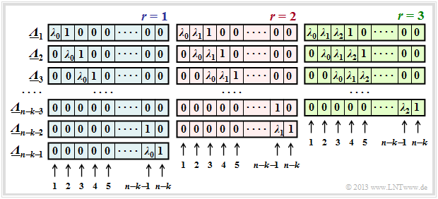
Die Eigenschaft des Error Locator Polynoms, dass ${\it \Lambda}(\alpha^{i})$ nur für $e_i ≠ 0$ $(i$–tes Symbol verfälscht$)$ gleich Null ist, bleibt erhalten, wenn man ${\it \Lambda}(x)$ mit beliebigen Potenzen von $x$ multipliziert. Jede Multiplikation mit $x$ bedeutet für den ELP–Koeffizientenvektor eine Verschiebung um eine Stelle nach rechts.
$\text{Definition:}$ Die $\text{verallgemeinerten ELP–Koeffizientenvektoren}$ $\underline {\it \Lambda }_l$ ergeben sich durch sukzessive Verschiebungen gegenüber $\underline {\it \Lambda }_l$:
- \[{\it \Lambda}_l(x)=x^l \cdot \prod_{i\hspace{0.05cm}\in \hspace{0.05cm} I_{\rm FP} }(x-\alpha^i) =x^l \cdot \big [{\it \lambda}_0 + \lambda_1 \cdot x+\ldots+{\it \lambda}_{r-1} \cdot x^{r-1}+x^r \big ]\hspace{0.05cm}.\]
In dieser Definitionsgleichung entspricht $\underline {\it \Lambda }_1$ dem bisherigen $\underline {\it \Lambda }$.
Die Grafik zeigt die Belegung unter der Annahme von $r$ Fehlerstellen im Fehlervektor $\underline {e}$ für
- $r=1$ im linken Bereich (mit blauer Hinterlegung),
- $r=2$ im mittleren Bereich (mit roter Hinterlegung),
- $r=3$ im rechten Bereich (mit grüner Hinterlegung).
Man erkennt:
- Die Länge aller $\underline {\it \Lambda }_l$ ist stets $n-k$. Jeder Vektor beinhaltet jeweils $r$ Koeffizienten $\lambda_0$, $\lambda_1$, ... , $\lambda_{r-1}$ ⇒ $0 ≤ i < r$ und eine Eins. Der Rest eines jeden Vektors ist mit Nullen aufgefüllt.
- Für jedes $r$ gibt es genau $n-k-r$ Koeffizientenvektoren $\underline {\it \Lambda }_l$, wobei sich $\underline {\it \Lambda }_l$ aus $\underline {\it \Lambda }_{l-1}$ stets durch Rechtsverschiebung um eine Position ergibt. Der Vektor $\underline {\it \Lambda }_{n-k-r}$ endet immer mit einer $1$.
- Das Gleichungssystem $\underline {\it \Lambda }_l \cdot \underline {s}^{\rm T} = 0 $ führt deshalb zu $n-k-r$ Gleichungen. Der gewählte Ansatz für $r$ ist nur dann richtig, wenn alle Gleichungen zu den gleichen Ergebnissen für $\lambda_0$, ... , $\lambda_{r-1}$ führen.
- Ist dies nicht der Fall, so muss man $r$ erhöhen und damit ein neues Gleichungssystem bearbeiten, und zwar solange, bis sich aus allen Gleichungen für das aktuelle $r$ eine eindeutige Lösung ergibt.
- Ist schließlich $r$ größer als die Korrekturfähigkeit $t$ des Codes, so kann die Berechnung beendet werden. Das anstehende Empfangswort $\underline {y}$ ist dann nicht decodierbar.
$\text{Beispiel 4:}$ Es gelten weiterhin die im $\text{Beispiel 2}$ genannten Voraussetzungen:
- Dort wurde aufgrund des Syndroms $\underline {s} = (\alpha^5,\alpha^2,\alpha^3,\alpha^1) ≠ \underline {0}$ auch nachgewiesen, dass der Empfangsvektor $\underline {y}$ verfälscht wurde ⇒ Fehlervektor $\underline {e} \ne \underline {0}$.
- Nicht bekannt ist allerdings die tatsächliche Symbolfehleranzahl $r$.
Unter der Annahme eines einzigen falschen Symbols $(r= 1)$ erhält man folgendes Gleichungssystem (hier in Matrixform geschrieben):
- \[\big ({ \boldsymbol{\it \Lambda } }_l \big) \cdot \underline {s} ^{\rm T}= \begin{pmatrix} \lambda_0 & 1 & 0 & 0 \\ 0 & \lambda_0 & 1 & 0 \\ 0 & 0 & \lambda_0 & 1 \end{pmatrix} \cdot \begin{pmatrix} \alpha^5\\ \alpha^2\\ \alpha^3\\ \alpha \end{pmatrix} \stackrel{!}{=} \begin{pmatrix} 0\\ 0\\ 0 \end{pmatrix} \hspace{0.05cm}.\]
Dieses Gleichungssystem liefert drei unterschiedliche Lösungen für $\lambda_0$, was nicht zielführend ist:
- \[\text{Zeile 1:}\hspace{0.5cm}\alpha^5 \cdot \lambda_0 + \alpha^2 = 0 \hspace{0.3cm} \Rightarrow \hspace{0.3cm} \lambda_0 = \alpha^{2-5}= \alpha^{-3}= \alpha^{4}\hspace{0.05cm},\]
- \[\text{Zeile 2:}\hspace{0.5cm}\alpha^2 \cdot \lambda_0 + \alpha^3 = 0 \hspace{0.3cm} \Rightarrow \hspace{0.3cm} \lambda_0 = \alpha^{3-2}= \alpha\hspace{0.05cm},\]
- \[\text{Zeile 3:}\hspace{0.5cm}\alpha^3 \cdot \lambda_0 + \alpha^1 = 0 \hspace{0.3cm} \Rightarrow \hspace{0.3cm} \lambda_0 = \alpha^{1-3}= \alpha^{-2} = \alpha^{5} \hspace{0.05cm}.\]
Deshalb stellen wir nun ein weiteres Gleichungssystem auf, und zwar unter der Annahme $r = 2$:
- \[\big ({ \boldsymbol{\it \Lambda } }_l \big) \cdot \underline {s} ^{\rm T}= \begin{pmatrix} \lambda_0 & \lambda_1 & 1 & 0 \\ 0 & \lambda_0 & \lambda_1 & 1 \end{pmatrix} \cdot \begin{pmatrix} \alpha^5\\ \alpha^2\\ \alpha^3\\ \alpha \end{pmatrix} \stackrel{!}{=} \begin{pmatrix} 0\\ 0 \end{pmatrix}\hspace{0.05cm}. \]
Dies führt zu zwei Gleichungen für $\lambda_0$ und $\lambda_1$:
- \[\alpha^5 \cdot \lambda_0 + \alpha^2 \cdot \lambda_1 + \alpha^3 = 0 \hspace{0.05cm},\hspace{0.5cm}\alpha^2 \cdot \lambda_0 + \alpha^3 \cdot \lambda_1 + \alpha^1 = 0 \hspace{0.05cm}.\]
Dieses Gleichungssystem ist nun eindeutig lösbar. Man erhält $\lambda_0 = \alpha^2$ und $\lambda_1 = \alpha^6$. Das bedeutet:
- Die Annahme, dass tatsächlich $r = 2$ Positionen des Empfangsvektors $\underline {y}$ verfälscht wurden, ist richtig.
- Man weiß aber noch nicht, welche Positionen verfälscht wurden. Soviel vorneweg:
- Es sind nicht die Symbolpositionen 2 und 6, sondern die Positionen 0 und 2, wie im folgenden $\text{Beispiel 5}$ (nächste Seite) gezeigt wird.
Step (C): Localization of the error locations
Nach Abarbeitung von Schritt $\rm(B)$ sind bekannt:
- die Anzahl $r$ der Fehlerstellen $e_i ≠ 0$ im Vektor $\underline {e} = (e_0, \hspace{0.05cm}\text{... }\hspace{0.05cm}, e_i, \hspace{0.05cm}\text{... }\hspace{0.05cm}, e_{n-1})$,
- die Koeffizienten $\lambda_0, \hspace{0.05cm}\text{... }\hspace{0.05cm} , \lambda_{r-1}$ des Error Locator Polynoms.
Zu bestimmen ist nun noch die Menge der Fehlerpositionen: $I_{\rm FP} = \{ i \hspace{0.1cm}| \hspace{0.1cm} e_i \ne 0,\hspace{0.1cm} 0 \le i < n \}\hspace{0.05cm}.$
Hierzu gibt es zwei Möglichkeiten (beide Verfahren werden im folgenden Beispiel angewendet):
- die so genannte Chien–Suche, in dem man durch Einsetzen der möglichen Codesymbole außer dem Nullsymbol ⇒ $(\alpha^0, \text{... }, \alpha^i, \text{... },\alpha^{n-1})$ in das Error Locator Polynom dessen Nullstellen ermittelt,
- die Auswertung der Gleichung $\underline {L} = (L_0, \text{... }, L_i, \text{... },L_{n-1} ) = \underline {\it \Lambda } \cdot { \boldsymbol{\rm H }}$ mit der Abkürzung $L_i = {\it \Lambda}(\alpha^i)$.
$\text{Beispiel 5:}$ Im $\text{Beispiel 4}$ wurde entsprechend den in $\text{Beispiel 2}$ genannten Randbedingungen ermittelt, dass
- $r= 2$ Symbolfehler vorliegen, und
- die ELP–Koeffizienten $\lambda_0 = \alpha^2$ und $\lambda_1 = \alpha^6$ lauten.
Damit ergibt sich folgendes Error Locator Polynom:
- \[{\it \Lambda}(x)=x \cdot \big [{\it \lambda}_0 + \lambda_1 \cdot x+x^2 \big ] =x \cdot \big [\alpha^2 + \alpha^6 \cdot x+x^2 \big ]\hspace{0.05cm}.\]
Entsprechend der Chien–Suche erhält man
- \[{\it \Lambda}(\alpha^0)\hspace{0.15cm} = \hspace{0.15cm}\alpha^0 \cdot \big [ \alpha^2 + \alpha^6 \cdot 1 + 1 \big ] = \alpha^2 + (\alpha^2 + 1) + 1 = 0 \hspace{0.3cm} \Rightarrow \hspace{0.3cm}{ \boldsymbol{\rm Nullstelle} }\hspace{0.05cm},\]
- \[{\it \Lambda}(\alpha^1)\hspace{0.15cm} = \hspace{0.15cm}\alpha^1 \cdot \big [\alpha^2 + \alpha^6 \cdot \alpha^1 + \alpha^2\big ]= \alpha^1 \hspace{0.3cm} \Rightarrow \hspace{0.3cm}{\rm Keine\hspace{0.15cm} Nullstelle}\hspace{0.05cm},\]
- \[{\it \Lambda}(\alpha^2)\hspace{0.15cm} = \hspace{0.15cm}\alpha^2 \cdot \big [ \alpha^2 + \alpha^6 \cdot \alpha^2 + \alpha^4 \big ] =\alpha^4 + \alpha^{10} + \alpha^6 = \text{...} = \hspace{0.15cm}0 \hspace{0.3cm} \Rightarrow \hspace{0.3cm}{ \boldsymbol{\rm Nullstelle} }\hspace{0.05cm}.\]
Damit sind die beiden Fehlerpositionen mit $i = 0$ und $i = 2$ gefunden ⇒ der Fehlervektor lautet: $\underline {e} = (e_0, 0, e_2, 0, 0, 0, 0)$ .
Die Vektorgleichung $\underline {L} = \underline {\it \Lambda } \cdot { \boldsymbol{\rm H } }$ liefert das gleiche Ergebnis in kompakterer Form:
- \[\underline {L} = \underline{\it \Lambda} \cdot { \boldsymbol{\rm H } } = (\alpha^2, \alpha^6, 1, 0) \cdot \begin{pmatrix} 1 & \alpha^1 & \alpha^2 & \alpha^3 & \alpha^4 & \alpha^5 & \alpha^6 \\ 1 & \alpha^2 & \alpha^4 & \alpha^6 & \alpha^1 & \alpha^3 & \alpha^5 \\ 1 & \alpha^3 & \alpha^6 & \alpha^3 & \alpha^5 & \alpha^1 & \alpha^4 \\ 1 & \alpha^4 & \alpha^1 & \alpha^5 & \alpha^2 & \alpha^6 & \alpha^3 \end{pmatrix} \]
- \[ \Rightarrow \hspace{0.3cm} \underline {L} = (\alpha^2,\alpha^3,\alpha^4,\alpha^5,\alpha^6,1 ,\alpha^1) + (\alpha^6,\alpha^1,\alpha^3,\alpha^5,1 ,\alpha^2,\alpha^4)+(1, \alpha^3,\alpha^6,\alpha^3,\alpha^5,\alpha^1,\alpha^4) \]
- \[ \Rightarrow \hspace{0.3cm} \underline {L} = (0,\alpha^1,0,\alpha^3,\alpha^3,\alpha^5,\alpha^1)\hspace{0.3cm} \Rightarrow \hspace{0.3cm} L_0 = L_2 = 0 \hspace{0.3cm} \Rightarrow \hspace{0.3cm} \underline {e} = (e_0, 0, e_2, 0, 0, 0, 0)\hspace{0.05cm}.\]
Das Beispiel wird mit dem $\text{Beispiel 6}$ auf der nächsten Seite fortgesetzt.
Step (D): Final error correction
Im letzten Schritt müssen nun nur noch die $r$ Symbolfehler korrigiert werden, deren Positionen nach Beendigung von Schritt $\rm (C)$ bekannt sind:
- Markiert man die Fehlerpositionen im Empfangswort $\underline {y}$ als Auslöschungen $\rm E$ (Erasures ), so kann das zugehörige Codewort $\underline {z}$ entsprechend der Beschreibung im Kapitel Reed–Solomon–Decodierung beim Auslöschungskanal gefunden werden.
- Eine zweite Möglichkeit bietet die Bestimmung des Fehlervektors $\underline {e}$ aus der Gleichung $\underline {e} \cdot \boldsymbol{\rm H }^{\rm T} = \underline {s}$ und die Korrektur entsprechend $\underline {z} = \underline {y} - \underline {e} $. Dieses Verfahren liegt dem folgenden Beispiel zugrunde.
$\text{Beispiel 6:}$ Wir betrachten wieder den $\text{RSC (7, 3, 5)}_8$. Im $\text{Beispiel 2}$ wurde
- das Empfangswort mit $\underline{y}=\big (\alpha^3,\hspace{0.05cm} 1,\hspace{0.05cm} 0, \hspace{0.05cm}\alpha^1, \hspace{0.05cm} \alpha^2, \hspace{0.05cm} \alpha^5, \hspace{0.05cm} \alpha^5 \big)$ vorgegeben, und
- daraus das Syndrom $\underline{s}=\big (\alpha^5,\hspace{0.05cm}\alpha^2, \hspace{0.05cm} \alpha^3, \hspace{0.05cm} \alpha^1\big)$ ermittelt.
Nach den Berechnungen im $\text{Beispiel 5}$ lautet der Fehlervektor $\underline {e} = (e_0, 0, e_2, 0, 0, 0, 0)$.
Aus $\underline {e} \cdot \boldsymbol{\rm H }^{\rm T} = \underline {s}$ erhält man nun folgende Bestimmungsgleichungen für die Fehlerwerte $e_0$ und $e_2$:
- \[\underline {e} \cdot \boldsymbol{\rm H }^{\rm T}= \begin{pmatrix} e_0 & 0 & e_2 & 0 & 0 & 0 & 0 \end{pmatrix}\cdot \begin{pmatrix} 1 & 1 & 1 & 1 \\ \alpha^1 & \alpha^2 & \alpha^3 & \alpha^4\\ \alpha^2 & \alpha^4 & \alpha^6 & \alpha^1\\ \alpha^3 & \alpha^6 & \alpha^2 & \alpha^{5}\\ \alpha^4 & \alpha^1 & \alpha^{5} & \alpha^{2}\\ \alpha^5 & \alpha^{3} & \alpha^{1} & \alpha^{6}\\ \alpha^6 & \alpha^{5} & \alpha^{4} & \alpha^{3} \end{pmatrix} \stackrel{!}{=} \underline {s} = \begin{pmatrix} \alpha^5 & \alpha^2 & \alpha^3 & \alpha^1 \end{pmatrix} \]
- \[\Rightarrow \hspace{0.3cm}e_0 \cdot (1, 1, 1, 1) + e_2 \cdot ( \alpha^2, \alpha^4, \alpha^6, \alpha^1)\stackrel{!}{=} ( \alpha^5, \alpha^2, \alpha^3, \alpha^1)\]
- \[\Rightarrow \hspace{0.3cm} e_0 + e_2 \cdot \alpha^2 = \alpha^5\hspace{0.05cm},\hspace{0.2cm} e_0 + e_2 \cdot \alpha^4 = \alpha^2\hspace{0.05cm},\hspace{0.2cm} e_0 + e_2 \cdot \alpha^6 = \alpha^3\hspace{0.05cm},\hspace{0.2cm} e_0 + e_2 \cdot \alpha^1 = \alpha^1\hspace{0.05cm}.\]
Alle Gleichungen führen zum Ergebnis $e_0 = 1$ und $e_2 =\alpha^2$.
Damit lautet das korrigierte Codewort mit $\underline {y} = (\alpha^3,\hspace{0.05cm} 1,\hspace{0.05cm} 0,\hspace{0.05cm} \alpha^1,\hspace{0.05cm} \alpha^2,\hspace{0.05cm} \alpha^5,\hspace{0.05cm} \alpha^5)$ und $\underline {e}= (1,\hspace{0.05cm} 0,\hspace{0.05cm} \alpha^2,\hspace{0.05cm} 0,\hspace{0.05cm} 0,\hspace{0.05cm} 0,\hspace{0.05cm} 0)$:
- \[\underline {z} = \underline {y} - \underline {e} = \underline {y} + \underline {e}= (\alpha^1,\hspace{0.03cm} 1,\hspace{0.03cm} \alpha^2,\hspace{0.03cm} \alpha^1,\hspace{0.03cm} \alpha^2,\hspace{0.03cm} \alpha^5,\hspace{0.03cm} \alpha^5)\hspace{0.05cm}. \]
Dieses ist ein gültiges Codewort von $\text{RSC (7, 3, 5)}_8$.
Fast Reed-Solomon decoding
Die Klasse der Reed–Solomon–Codes wurde bereits im Jahre 1960 durch die Veröffentlichung [RS60][1] eingeführt. Ihre effiziente Decodierung war jedoch erst ein bis zwei Jahrzehnte später möglich.
Auf den letzten Seiten haben wir den so genannten Petersen–Algorithmus inklusive der Chien–Suche am Beispiel des $\text{RSC (7, 3, 5)}_8$ demonstriert, der bis zu $t = 2$ Fehler korrigieren kann. Im Mittelpunkt des Decodiervorgangs stand dabei das Aufstellen und Lösen der Schlüsselgleichung (englisch: Error Locator Polynom ), wobei die Nullstellen eines Grad–$2$–Polynoms im Körper $\rm GF(7)$ gefunden werden mussten. Es war zu erkennen, dass schon diese algebraische Decodierung mit großem Aufwand verbunden ist.
Bei den in Praxis eingesetzten Codes mit großer Codewortlänge $n$ und hoher Korrekturfähigkeit $t$ würde der Decodieraufwand explodieren, wenn nicht schnellere Decodieralgorithmen gefunden worden wären. So müssen beim Reed–Solomon–Code $\text{RSC (255, 223, 33)}_{256}$, der schon früh im ESA/NASA–Standard zur Satellitenübertragung genannt wurde, zur Decodierng eines einzigen Codewortes bis zu $t = 16$ Nullstellen im Körper $\rm GF(255)$ gefunden werden. Und das in Echtzeit!
Ab Ende der 1960er Jahre haben sich viele Wissenschaftler um schnellere Decodieralgorithmen für Reed–Solomon–Codes bemüht:
- Beim Berlekamp–Massey–Algorithmus $\rm (BMA)$ wird die Schlüsselgleichung $\underline {\it \Lambda} \cdot \underline{s }^{\rm T} = 0$ als rückgekoppeltes Schieberegister dargestellt, siehe zum Beispiel [Mas69][2], [Fri96][3] und [Bos98][4]. Das Problem wird damit auf die Synthese eines autoregressiven Filters zurückgeführt. Dieser Algorithmus arbeitet wesentlich schneller als der (leichter durchschaubare) Petersen–Algorithmus.
- Etwas später wurde in [SK+75][5] ein Decodierverfahren vorgeschlagen, das auf dem Euklidischen Algorithmus basiert. Dieser liefert den größten gemeinsamen Teiler zweier ganzer Zahlen, was zur Decodierung genutzt wird. Der Euklidische Algorithmus ist vergleichbar schnell wie der $\rm BMA$. Genauere Informationen finden Sie wieder in [Bos98][4] und [Fri96][3].
- Weitere effiziente Decodiermethoden von Reed–Solomon–Codes arbeiten im Frequenzbereich unter Verwendung der Diskreten Fouriertransformation $\rm (DFT)$ im Körper ${\rm GF}(n)$.
Die Grundzüge der Reed–Solomon–Fehlerkorrektur wurden bereits in den 1960er Jahren entwickelt. Aber bis in die heutige Zeit (2013) ist die (möglichst schnelle) algebraische Decodierung dieser Codes ein hochaktuelles Forschungsgebiet.
Exercises for the chapter
Aufgabe 2.12: Decodierung beim RSC (7, 4, 4) zur Basis 8
Aufgabe 2.12Z: Reed–Solomon–Syndromberechnung
Aufgabe 2.13: Decodierung beim RSC (7, 3, 5) zur Basis 8
Aufgabe 2.14: Petersen–Algorithmus
Quellenverzeichnis
- ↑ Reed, I.S.; Solomon, G.: Polynomial Codes over Certain Finite Fields. J. Siam, Vol. 8, pp. 300–304, 1960.
- ↑ Massey, J.L.: Shift Register Synthesis and BCH Decoding.. IEEE Trans. on Information Theory, vol. IT-15, pp. 122–127, Jan. 1969.
- ↑ 3.0 3.1 Friedrichs, B.: Kanalcodierung – Grundlagen und Anwendungen in modernen Kommunikations- systemen. Berlin – Heidelberg: Springer, 1996.
- ↑ 4.0 4.1 Bossert, M.: Kanalcodierung. Stuttgart: B. G. Teubner, 1998.
- ↑ Sugiyama, Y.; Kashara, M.; Hirasawa, S.; Namekawa, T.: A Method for Solving Key Equation for Decoding Goppa Codes. Information and Control, Vol. 27, pp. 87–99, 1975.


