Principle of Pseudo-Ternary Coding
Open Applet in new Tab Deutsche Version Öffnen
Contents
Applet Description
Das Applet behandelt die Eigenschaften der bekanntesten Pseudoternärcodes, nämlich:
- Bipolarcode erster Ordnung bzw. $\rm AMI$–Code (von: Alternate Mark Inversion), gekennzeichnet durch die Parameter $N_{\rm C} = 1, \ K_{\rm C} = +1$,
- Duobinärcode, $(\rm DUOB)$, Codeparameter: $N_{\rm C} = 1, \ K_{\rm C} = -1$,
- Bipolarcode zweiter Ordnung $(\rm BIP2)$, Codeparameter: $N_{\rm C} = 2, \ K_{\rm C} = +1$.
Am Eingang liegt die redundanzfreie binäre bipolare Quellensymbolfolge $\langle \hspace{0.05cm}q_\nu \hspace{0.05cm}\rangle \ \in \{+1, -1\}$ ⇒ Rechtecksignal $q(t)$ an. Verdeutlicht wird die Generierung
- der binär–vorcodierten Folge $\langle \hspace{0.05cm}b_\nu \hspace{0.05cm}\rangle \ \in \{+1, -1\}$, dargestellt durch das ebenfalls redundanzfreie binäre bipolare Rechtecksignal $b(t)$,
- der pseudoternären Codefolge $\langle \hspace{0.05cm}c_\nu \hspace{0.05cm}\rangle \ \in \{+1,\ 0, -1\}$, dargestellt durch das redundante ternäre bipolare Rechtecksignal $c(t)$,
- das gleichermaßen redundante ternäre Sendesignal $s(t)$, gekennzeichnet durch die Amplitudenkoeffizienten $a_\nu $, und den (Sende–) Grundimpuls $g(t)$:
- $$s(t) = \sum_{\nu = -\infty}^{+\infty} a_\nu \cdot g( t - \nu \cdot T)\hspace{0.05cm}.$$
Der Grundimpuls $g(t)$ – im Applet "Rechteck", "Nyquist" und "Wurzel–Nyquist" – bestimmt nicht nur die Form des Sendesignals, sondern auch den Verlauf
- der Autokorrelationsfunktion $\rm (AKF)$ $\varphi_s (\tau)$ und
- des zugehörigen Leistungsdichtespektrums $\rm (LDS)$ ${\it \Phi}_s (f)$.
Das Applet zeigt auch, dass das gesamte Leistungsdichtespektrum ${\it \Phi}_s (f)$ aufgeteilt werden kann in den Anteil ${\it \Phi}_a (f)$, der die statistischen Bindungen der Amplitudenkoeffizienten $a_\nu$ berücksichtigt, und das Energiedichtespektrum $ {\it \Phi}^{^{\hspace{0.08cm}\bullet}}_{g}(f) = |G(f)|^2 $, gekennzeichnet durch die Impulsform $g(t)$.
Anmerkung: Im Applet wird kein Unterschied zwischen den Codersymbolen $c_\nu \in \{+1,\ 0, -1\}$ und den Amplitudenkoeffizienten $a_\nu \in \{+1,\ 0, -1\}$ gemacht. Dabei sollte nicht vergessen werden, dass die $a_\nu$ stets Zahlenwerte sind, während für die Codersymbole auch die Notation $c_\nu \in \{\text{Plus},\ \text{Null},\ \text{Minus}\}$ zulässig wäre.
Theoretical Background
Allgemeine Beschreibung der Pseudoternärcodes
Bei der symbolweisen Codierung wird mit jedem ankommenden Quellensymbol $q_\nu$ ein Codesymbol $c_\nu$ erzeugt, das außer vom aktuellen Eingangssymbol $q_\nu$ auch von den $N_{\rm C}$ vorangegangenen Symbolen $q_{\nu-1}$, ... , $q_{\nu-N_{\rm C}} $ abhängt. $N_{\rm C}$ bezeichnet man als die Ordnung des Codes.
Typisch für eine symbolweise Codierung ist, dass
- die Symboldauer $T$ des Codersignals (und des Sendesignals) mit der Bitdauer $T_{\rm B}$ des binären Quellensignals übereinstimmt, und
- Codierung und Decodierung nicht zu größeren Zeitverzögerungen führen, die bei Verwendung von Blockcodes unvermeidbar sind.
Besondere Bedeutung besitzen Pseudomehrstufencodes – besser bekannt unter der englischen Bezeichnung Partial Response Codes.
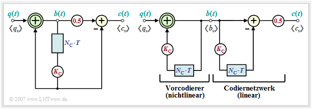
- Im Folgenden werden ausschließlich Pseudoternärcodes ⇒ Stufenzahl $M = 3$ betrachtet, die durch das Blockschaltbild entsprechend der linken Grafik beschreibbar sind.
- In der rechten Grafik ist ein Ersatzschaltbild angegeben, das für eine Analyse dieser Codes sehr gut geeignet ist.
Man erkennt aus den beiden Darstellungen:
- Der Pseudoternärcodierer kann in den nichtlinearen Vorcodierer und ein lineares Codiernetzwerk aufgespalten werden, wenn man – wie im rechten Ersatzschaltbild dargestellt – die Verzögerung um $N_{\rm C} \cdot T$ und die Gewichtung mit $K_{\rm C}$ zur Verdeutlichung zweimal zeichnet.
- Der nichtlineare Vorcodierer gewinnt durch eine Modulo–2–Addition ("Antivalenz") zwischen den Symbolen $q_\nu$ und $K_{\rm C} \cdot b_{\nu-N_{\rm C}} $ die vorcodierten Symbole $b_\nu$, die ebenfalls binär sind:
- $$q_\nu \in \{-1, +1\},\hspace{0.1cm} K_{\rm C} \in \{-1, +1\}\hspace{0.3cm}\Rightarrow \hspace{0.3cm}b_\nu \in \{-1, +1\}\hspace{0.05cm}.$$
- Die Symbole $b_\nu$ sind wie die Quellensymbole $q_\nu$ statistisch voneinander unabhängig. Der Vorcodierer fügt also keine Redundanz hinzu. Er gestattet aber eine einfachere Realisierung des Decoders und verhindert eine Fehlerfortpflanzung nach einem Übertragungsfehler.
- Die eigentliche Umcodierung von binär $(M_q = 2)$ auf ternär $(M = M_c = 3)$ bewirkt das lineare Codiernetzwerk durch die herkömmliche Subtraktion
- $$c(t) ={1}/{2} \cdot \big [b(t) - K_{\rm C} \cdot b(t- N_{\rm C}\cdot T)\big] \in \{-1, \ 0, +1\}\hspace{0.05cm},$$
- das durch folgende Impulsantwort bzw. Übertragungsfunktion bezüglich dem Eingangssignal $b(t)$ und dem Ausgangssignal $c(t)$ beschrieben werden kann:
- $$h_{\rm C}(t) = {1}/{2} \cdot \big [\delta(t) - K_{\rm C} \cdot \delta(t- N_{\rm C}\cdot T)\big] \ \ \ \circ\!\!-\!\!\!-\!\!\!-\!\!\bullet\ \ \ H_{\rm C}(f) ={1}/{2} \cdot \left [1 - K_{\rm C} \cdot {\rm e}^{- {\rm j}\hspace{0.05cm}\cdot\hspace{0.05cm} 2\pi \hspace{0.05cm}\cdot \hspace{0.05cm}N_{\rm C}\hspace{0.05cm}\cdot \hspace{0.05cm}T}\right]\hspace{0.05cm}. $$
- Die relative Coderedundanz ist für alle Pseudoternärcodes gleich. Setzt man in die allgemeine Definitionsgleichung $M_q=2$, $M_c=3$ und $T_c =T_q$ ein, so erhält man
- $$r_c = 1- \frac{R_q}{R_c} = 1- \frac{T_c}{T_q} \cdot \frac{{\rm log_2}\hspace{0.05cm} (M_q)}{{\rm log_2} \hspace{0.05cm}(M_c)} = 1- \frac{T_c}{T_q \cdot {\rm log_2} \hspace{0.05cm}(M_c)}\hspace{0.5cm}\Rightarrow \hspace{0.5cm} r_c = 1 -1/\log_2\hspace{0.05cm}(3) \approx 36.9 \%\hspace{0.05cm}.$$
Das $\text{Sendesignal aller Pseudoternärcodes}$ wird im Folgenden stets wie folgt dargestellt:
- $$s(t) = \sum_{\nu = -\infty}^{+\infty} a_\nu \cdot g( t - \nu \cdot T)\hspace{0.05cm}.$$
- Die Eigenschaft des aktuellen Pseudoternärcodes spiegelt sich in den statistischen Bindungen zwischen den $a_\nu$ wider. In allen Fällen gilt $a_\nu \in \{-1, \ 0, +1\}$.
- Der Sendegrundimpuls $g(t)$ stellt zum einen die erforderliche Energie bereit, hat aber auch Einfluss auf die statistischen Bindungen innerhalb des Signals.
- Im Programm ausgewählt werden kann neben dem NRZ–Rechteckimpuls $g_{\rm R}(t)$:
- der Nyquistimpuls ⇒ Impulsantwort des Cosinus–Rolloff–Tiefpasses mit Rolloff–Faktor $r$:
- $$g_{\rm Nyq}(t)={\rm const.} \cdot \frac{\cos(\pi \cdot r\cdot t/T)}{1-(2\cdot r\cdot t/T)^2} \cdot {\rm si}(\pi \cdot t/T) \ \ \ \circ\!\!-\!\!\!-\!\!\!-\!\!\bullet\ \ \ G_{\rm Nyq}(f),$$
- der Wurzel–Nyquistimpuls ⇒ Impulsantwort des Wurzel–Cosinus–Rolloff–Tiefpasses mit Rolloff–Faktor $r$:
- $$g_{\sqrt{\rm Nyq} }(t)\ \ \ \circ\!\!-\!\!\!-\!\!\!-\!\!\bullet\ \ \ G_{\sqrt{\rm Nyq} }(f)={\rm const.} \cdot \sqrt{G_{\rm Nyq}(f)} .$$
Eigenschaften des AMI-Codes
Die Pseudoternärcodes unterscheiden sich in den Parametern $N_{\rm C}$ und $K_{\rm C}$. Der bekannteste Vertreter ist der Bipolarcode erster Ordnung mit den Codeparametern $N_{\rm C} = 1$ und $K_{\rm C} = 1$, der auch unter der Bezeichnung AMI–Code (von: Alternate Mark Inversion) bekannt ist.
Dieser wird zum Beispiel bei ISDN (Integrated Services Digital Networks) auf der so genannten $S_0$–Schnittstelle eingesetzt.
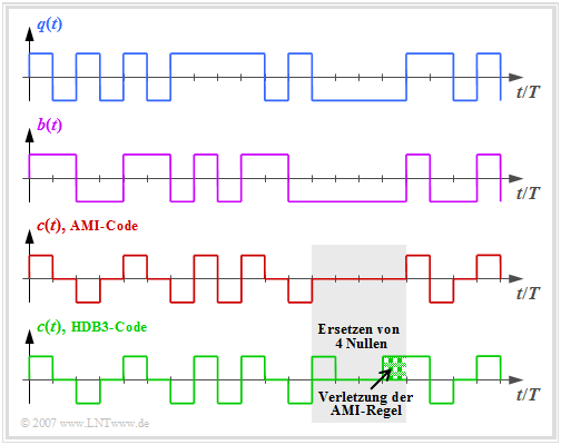
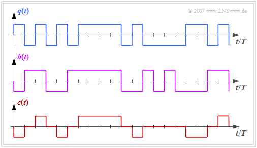
Die Grafik zeigt oben das binäre Quellensignal $q(t)$. Im zweiten und dritten Diagramm sind dargestellt:
- das ebenfalls binäre Signal $b(t)$ nach dem Vorcodierer, und
- das Codersignal $c(t) = s(t)$ des AMI–Codes.
Man erkennt das einfache AMI–Codierprinzip:
- Jeder Binärwert "-1" von $q(t)$ ⇒ Symbol $\rm L$ wird durch den ternären Koeffizienten $a_\nu = 0$ codiert.
- Der Binärwert "+1" von $q(t)$ ⇒ Symbol $\rm H$ wird alternierend mit $a_\nu = +1$ und $a_\nu = -1$ dargestellt.
Damit wird sichergestellt, dass im AMI–codierten Signal keine langen "+1"– und auch keine keine langen "–1"–Sequenzen enthalten sind, was bei einem gleichsignalfreien Kanal zu Problemen führen würde.
Dagegen ist das Auftreten langer Nullfolgen durchaus möglich, bei denen über einen längeren Zeitraum keine Taktinformation übertragen wird.
Um dieses zweite Problem zu vermeiden, wurden einige modifizierte AMI–Codes entwickelt, zum Beispiel der B6ZS–Code und der HDB3–Code:
- Beim HDB3–Code (grüne Kurve in obiger Grafik) werden vier aufeinanderfolgende Nullen im AMI–codierten Signal durch eine Teilsequenz ersetzt, die die AMI–Codierregel verletzt.
- Im grau hinterlegten Bereich ist dies die Folge "+ 0 0 +", da das letzte Symbol vor der Ersetzung ein "Minus" war.
- Damit ist beim HDB3–Code die Anzahl aufeinanderfolgender Nullen auf $3$ begrenzt und beim B6ZS–Code auf $5$.
- Der Decoder erkennt diese Codeverletzung und ersetzt "+ 0 0 +" wieder durch "0 0 0 0".
Zur AKF–Berechnung eines Digitalsignals
In der Versuchsdurchführung werden einige Größen und Zusamenhänge verwendet, die hier kurz eräutert werden sollen:
- Das (zeitlich unbegrenzte) Digitalsignal beinhaltet sowohl die Quellenstatistik $($Amplitudenkoeffizienten $a_\nu$) als auch die Sendeimpulsform $g(t)$:
- $$s(t) = \sum_{\nu = -\infty}^{+\infty} a_\nu \cdot g ( t - \nu \cdot T)\hspace{0.05cm}.$$
- Ist $s(t)$ die Musterfunktion eines stationären und ergodischen Zufallsprozesses, so gilt für die Autokorrelationsfunktion $\rm (AKF)$:
- $$\varphi_s(\tau) = {\rm E}\big [s(t) \cdot s(t + \tau)\big ] = \sum_{\lambda = -\infty}^{+\infty}{1}/{T} \cdot \varphi_a(\lambda)\cdot\varphi^{^{\bullet} }_{gs}(\tau - \lambda \cdot T)\hspace{0.05cm}.$$
- Diese Gleichung beschreibt die Faltung der diskreten AKF $\varphi_a(\lambda) = {\rm E}\big [ a_\nu \cdot a_{\nu + \lambda}\big]$ der Amplitudenkoeffizienten mit der Energie–AKF des Grundimpulses:
- $$\varphi^{^{\bullet} }_{g}(\tau) = \int_{-\infty}^{+\infty} g ( t ) \cdot g ( t + \tau)\,{\rm d} t \hspace{0.05cm}.$$
- Der Punkt soll darauf hinweisen, dass $\varphi^{^{\bullet} }_{g}(\tau)$ die Einheit einer Energie besitzt, während $\varphi_s(\tau)$ eine Leistung angibt und $\varphi_a(\lambda)$ dimensionslos ist.
Zur LDS-Berechnung eines Digitalsignals
Die Entsprechungsgröße zur AKF ist im Frequenzbereich das Leistungsdichtespektrum $\rm (LDS)$ ${\it \Phi}_s(f)$, das mit $\varphi_s(\tau)$ über das Fourierintegral fest verknüpft ist:
- $$\varphi_s(\tau) \hspace{0.4cm}\circ\!\!-\!\!\!-\!\!\!-\!\!\bullet \hspace{0.4cm} {\it \Phi}_s(f) = \int_{-\infty}^{+\infty} \varphi_s(\tau) \cdot {\rm e}^{- {\rm j}\hspace{0.05cm} 2 \pi f \hspace{0.02cm} \tau} \,{\rm d} \tau \hspace{0.05cm}.$$
- Das Leistungsdichtespektrum ${\it \Phi}_s(f)$ kann unter Berücksichtigung der Dimensionsbereinigung $(1/T)$ als Produkt zweier Funktionen dargestellt werden:
- $${\it \Phi}_s(f) = {\it \Phi}_a(f) \cdot {1}/{T} \cdot |G_s(f)|^2 \hspace{0.05cm}.$$
- Der erste Term ${\it \Phi}_a(f)$ ist dimensionslos und beschreibt die spektrale Formung des Sendesignals durch die statistischen Bindungen der Quelle:
- $$\varphi_a(\lambda) \hspace{0.4cm}\circ\!\!-\!\!\!-\!\!\!-\!\!\bullet \hspace{0.4cm}{\it \Phi}_a(f) = \sum_{\lambda = -\infty}^{+\infty}\varphi_a(\lambda)\cdot {\rm e}^{- {\rm j}\hspace{0.05cm} 2 \pi f \hspace{0.02cm} \lambda \hspace{0.02cm}T} = \varphi_a(0) + 2 \cdot \sum_{\lambda = 1}^{\infty}\varphi_a(\lambda)\cdot\cos ( 2 \pi f \lambda T) \hspace{0.05cm}.$$
- ${\it \Phi^{^{\hspace{0.08cm}\bullet}}_{g}}(f)$ berücksichtigt die spektrale Formung durch $g(t)$. Je schmaler dieser ist, desto breiter ist $\vert G(f) \vert^2$ und um so größer ist damit der Bandbreitenbedarf:
- $$\varphi^{^{\hspace{0.05cm}\bullet}}_{g}(\tau) \hspace{0.4cm}\circ\!\!-\!\!\!-\!\!\!-\!\!\bullet \hspace{0.4cm} {\it \Phi}^{^{\hspace{0.08cm}\bullet}}_{g}(f) = |G(f)|^2 \hspace{0.05cm}.$$
- Das Energiedichtespektrum ${\it \Phi^{^{\hspace{0.08cm}\bullet}}_{g}}(f)$ hat die Einheit $\rm Ws/Hz$ und das Leistungsdichtespektrum ${\it \Phi_{s}}(f)$ nach der Division durch den Symbolabstand $T$ die Einheit $\rm W/Hz$.
Leistungsdichtespektrum des AMI-Codes
Der Frequenzgang des linearen Codiernetzwerks eines Pseudoternärcodes lautet allgemein:
- $$H_{\rm C}(f) = {1}/{2} \cdot \big [1 - K_{\rm C} \cdot {\rm e}^{-{\rm j}\hspace{0.03cm}\cdot \hspace{0.03cm} 2\pi\hspace{0.03cm}\cdot \hspace{0.03cm}f \hspace{0.03cm}\cdot \hspace{0.03cm} N_{\rm C}\hspace{0.03cm}\cdot \hspace{0.03cm}T} \big] ={1}/{2} \cdot \big [1 - K \cdot {\rm e}^{-{\rm j}\hspace{0.03cm}\cdot \hspace{0.03cm} \alpha} \big ]\hspace{0.05cm}.$$
Damit ergibt sich für das Leistungsdichtespektrum (LDS) der Amplitudenkoeffizienten $(K$ und $\alpha$ sind Abkürzungen entsprechend obiger Gleichung$)$:
- $$ {\it \Phi}_a(f) = | H_{\rm C}(f)|^2 = \frac{\big [1 - K \cos (\alpha) + {\rm j}\cdot K \sin (\alpha) \big ] \big [1 - K \cos (\alpha) - {\rm j}\cdot K \sin (\alpha) \big ] }{4} = \text{...} = {1}/{4} \cdot \big [2 - 2 \cdot K \cdot \cos (\alpha) \big ] $$
- $$ \Rightarrow \hspace{0.3cm}{\it \Phi}_a(f) = | H_{\rm C}(f)|^2 = {1}/{2} \cdot \big [1 - K_{\rm C} \cdot \cos (2\pi f N_{\rm C} T)\big ] \hspace{0.4cm}\bullet\!\!-\!\!\!-\!\!\!-\!\!\circ \hspace{0.4cm} \varphi_a(\lambda \cdot T)\hspace{0.05cm}.$$
Insbesondere erhält man für das Leistungsdichtespektrum (LDS) des AMI–Codes $(N_{\rm C} = K_{\rm C} = 1)$:
- $${\it \Phi}_a(f) = {1}/{2} \cdot \big [1 - \cos (2\pi f T)\big ] = \sin^2 (\pi f T)\hspace{0.05cm}.$$
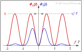
Die Grafik zeigt
- das LDS ${\it \Phi}_a(f)$ der Amplitudenkoeffizienten (rote Kurve), und
- das LDS ${\it \Phi}_s(f)$ des gesamten Sendesignals (blau), gültig für NRZ–Rechteckimpulse.
Man erkennt aus dieser Darstellung
- die Gleichsignalfreiheit des AMI–Codes, da ${\it \Phi}_a(f = 0) = {\it \Phi}_s(f = 0) = 0$ ist,
- die Leistung $P_{\rm S} = s_0^2/2$ des AMI–codierten Sendesignals (Integral über ${\it \Phi}_s(f)$ von $- \infty$ bis $+\infty$).
Hinweise:
- Das LDS von HDB3– und B6ZS–Code weicht von dem des AMI–Codes nur unwesentlich ab.
- Die hier behandelte Thematik können Sie sich mit dem interaktiven Applet Signale, AKF und LDS der Pseudoternärcodes verdeutlichen.
Eigenschaften des Duobinärcodes
Der Duobinärcode ist durch die Codeparameter $N_{\rm C} = 1$ und $K_{\rm C} = -1$ festgelegt. Damit ergibt sich für das Leistungsdichtespektrum (LDS) der Amplitudenkoeffizienten bzw. für das LDS des Sendesignals:
- $${\it \Phi}_a(f) ={1}/{2} \cdot \big [1 + \cos (2\pi f T)\big ] = \cos^2 (\pi f T)\hspace{0.05cm},$$
- $$ {\it \Phi}_s(f) = s_0^2 \cdot T \cdot \cos^2 (\pi f T)\cdot {\rm si}^2 (\pi f T)= s_0^2 \cdot T \cdot {\rm si}^2 (2 \pi f T) \hspace{0.05cm}.$$
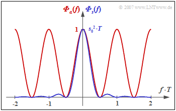
Die Grafik zeigt das Leistungsdichtespektrum
- der Amplitudenkoeffizienten ⇒ ${\it \Phi}_a(f)$ als rote Kurve,
- des gesamten Sendsignals ⇒ ${\it \Phi}_s(f)$ als blaue Kurve.
In der zweiten Grafik sind die Signale $q(t)$, $b(t)$ und $c(t) = s(t)$ skizziert. Wir verweisen hier wieder auf das Applet Signale, AKF und LDS der Pseudoternärcodes, das auch die Eigenschaften des Duobinärcodes verdeutlicht.
Aus diesen Darstellungen geht hervor:
- Beim Duobinärcode können beliebig viele Symbole mit gleicher Polarität ("+1" bzw. "–1") direkt aufeinanderfolgen.
- Deshalb gilt ${\it \Phi}_a(f = 0)=1$ und ${\it \Phi}_s(f = 0) = 1/2 \cdot s_0^2 \cdot T$.
- Dagegen tritt beim Duobinärcode die alternierende Folge " ... , +1, –1, +1, –1, +1, ... " nicht auf, die hinsichtlich Impulsinterferenzen besonders störend ist.
- Deshalb gilt beim Duobinärcode: ${\it \Phi}_s(f = 1/(2T) = 0$.
- Das Leistungsdichtespektrum ${\it \Phi}_s(f)$ des pseudoternären Duobinärcodes ist identisch mit dem LDS bei redundanzfreier Binärcodierung mit halber Rate $($Symboldauer $2T)$.
Exercises
- First, select the number $(1,\ 2, \text{...} \ )$ of the task to be processed. The number "$0$" corresponds to a "Reset": Same setting as at program start.
- A task description is displayed. The parameter values are adjusted. Solution after pressing "Show Solution".
(1) Consider and interpret the binary pre–coding of the $\text{AMI}$ code using the source symbol sequence $\rm C$ assuming $b_0 = +1$.
- The modulo–2 addition can also be taken as "antivalence". It holds $b_{\nu} = +1$, if $q_{\nu}$ and $b_{\nu - 1}$ differ, otherwise set $b_{\nu} = -1$ :
- $b_1 = (q_1 = +1)\ {\rm XOR}\ (b_0= +1) = -1,\ \ b_2 = (q_2 = -1)\ {\rm XOR}\ (b_1= -1) = -1,\ \ b_3 = (q_3 = -1)\ {\rm XOR}\ (b_2= -1) = -1,$
- $b_4 = (q_4 = +1)\ {\rm XOR}\ (b_3= -1) = +1,\ \ b_5 = (q_5 = +1)\ {\rm XOR}\ (b_4= +1) = -1,\ \ b_6 = (q_6 = +1)\ {\rm XOR}\ (b_5= -1) = +1,\ \ b_7 = b_8 = \text{...} = -1.$
- With the initial condition $b_0 = -1$ we get the negated sequence: $b_4 = b_6 =-1$. All others $b_\nu = +1$.
(2) Let $b_0 = +1$. Consider the AMI code sequence $\langle c_\nu \rangle$ of the source symbol sequence $\rm C$ and give their amplitude coefficients $a_\nu$.
- It holds: $a_1= 0.5 \cdot (b_1-b_0) = -1$, $a_2= 0.5 \cdot (b_2-b_1) =0$, $a_3= 0. 5 \cdot (b_3-b_2) =0$, $a_4= +1$, $a_5= -1$, $a_6= +1$, $a_7= -1$, $a_8= a_9 = \text{...} = 0$.
- In contrast to the pre–coding, the conventional addition (subtraction) is to be applied here and not the modulo–2 addition.
(3) Now consider the AMI coding for several random sequences. What rules can be derived from these experiments for the amplitude coefficients $a_\nu$ ?
- Each binary value "–1" of $q(t)$ ⇒ symbol $\rm L$ is encoded by the ternary coefficient $a_\nu = 0$. Any number of $a_\nu = 0$ can be consecutive.
- The binary value "+1" of $q(t)$ ⇒ symbol $\rm H$ is represented alternatively with $a_\nu = +1$ and $a_\nu = -1$ , starting with $a_\nu = -1$, if $b_0 = +1$.
- From the source symbol sequence $\rm A$ ⇒ $\langle \hspace{0.05cm}q_\nu \equiv +1 \hspace{0.05cm}\rangle$ the code symbol sequence $+1, -1, +1, -1, \text{...}$ . Long sequences $\langle \hspace{0.05cm}a_\nu \equiv +1 \hspace{0.05cm}\rangle$ or $\langle \hspace{0.05cm}a_\nu \equiv -1 \hspace{0.05cm}\rangle$ are shot out.
(4) Continue with AMI coding. Interpret the autocorrelation function $\varphi_a(\lambda)$ of the amplitude coefficients and the power density spectrum ${\it \Phi}_a(f)$.
- The discrete ACF $\varphi_a(\lambda)$ of the amplitude coefficients is only defined for integer $\lambda$ values. With AMI coding $(N_{\rm C}=1)$ holds: For $|\lambda| > 1$ ⇒ all $\varphi_a(\lambda)= 0$.
- $\varphi_a(\lambda = 0)$ is equal to the root mean square of the amplitude coefficients ⇒ $\varphi_a(\lambda = 0) = {\rm Pr}(a_\nu = +1) \cdot (+1)^2 + {\rm Pr}(a_\nu = -1) \cdot (-1)^2 = 0.5.$
- Only the combinations $(+1, -1)$ and $(-1, +1)$ contribute to the expected value ${\rm E}\big [a_\nu \cdot a_{\nu+1}\big]$ Result: $\varphi_a(\lambda = \pm 1)={\rm E}\big [a_\nu \cdot a_{\nu+1}\big]=-0.25.$
- The power density spectrum ${\it \Phi}_a(f)$ is the Fourier transform of the discrete ACF $\varphi_a(\lambda)$. Result: ${\it \Phi}_a(f) = {1}/{2} \cdot \big [1 - \cos (2\pi f T)\big ] = \sin^2 (\pi f T)\hspace{0.05cm}.$
- From ${\it \Phi}_a(f = 0) = 0$ follows: The AMI code is especially interesting for channels over which no DC component can be transmitted.
(5) We consider further AMI coding and rectangular pulses. Interpret the ACF $\varphi_s(\tau)$ of the transmission signal and the PDS ${\it \Phi}_s(f)$.
- $\varphi_s(\tau)$ results from the convolution of the discrete AKF $\varphi_a(\lambda)$ with $\varphi^{^{\hspace{0.05cm}\bullet}}_{g}(\tau)$. For rectangular pulses $($duration $T)$: The energy–AKF $\varphi^{^{\hspace{0.05cm}\bullet}}_{g}(\tau)$ is a triangle of duration $2T$.
- It holds $\varphi_s(\tau = 0)= \varphi_a(\lambda = 0) =0.5, \ \varphi_s(\pm T)= \varphi_a( 1) =-0. 25,\ , \ \varphi_s( \pm 2T)= \varphi_a(2) =0.$ Between these discrete values, $\varphi_{s}(\tau)$ is always linear.
- The PDS ${\it \Phi}_s(f)$ is obtained from ${\it \Phi}_a(f) = \sin^2(\pi f T)$ by multiplying with ${\it \Phi}^{^{\hspace{0.08cm}\bullet}}_{g}(f) = {\rm sinc}^2(f T).$ This does not change anything at the zeros of ${\it \Phi}_a(f)$ .
(6) What changes with respect to $s(t)$, $\varphi_s(\tau)$ and ${\it \Phi}_s(f)$ with the $\rm Nyquist$ pulse? Vary the roll–off factor here in the range $0 \le r \le 1$.
- A single Nyquist pulse can be represented with the source symbol sequence $\rm B$ in the $s(t)$ range. You can see equidistant zero crossings in the distance $T$.
- Also, for any AMI random sequence, the signal values $s(t=\nu \cdot T)$ for each $r$ correspond exactly to their nominal positions. Outside these points, there are deviations.
- In the special case $r=0$ the energy–LDS ${\it \Phi}^{^{\hspace{0.08cm}\bullet}}_{g}(f)$ is constant in the range $|f|<1/2T$. Accordingly, the energy–ACF ${\it \varphi}^{^{\hspace{0.08cm}\bullet}}_{g}(\tau)$ has a $\rm sinc$ shape.
- On the other hand, for larger $r$ the zeros of ${\it \varphi}^{^{\hspace{0.08cm}\bullet}}_{g}(\tau)$ are no longer equidistant, since although $G(f)$ satisfies the first Nyquist criterion, it does not ${\it \Phi}^{^{\hspace{0.08cm}\bullet}}_{g}(f)= [G(f)]^2$.
- The main advantage of the Nyquist pulse is the much smaller bandwidth. Here only the frequency range $|f| < (1+r)/(2T)$ has to be provided.
(7) Repeat the last experiment using the $\text{Root raised cosine}$ pulse instead of the Nyquist pulse. Interpret the results.
- In the special case $r=0$ the results are as in (6). ${\it \Phi}^{^{\hspace{0.08cm}\bullet}}_{g}(f)$ is constant in the range $|f|<1/2T$ and outside zero; ${\it \varphi}^{^{\hspace{0.08cm}\bullet}}_{g}(\tau)$ has a $\rm sinc$ shape.
- Also for larger $r$ the zeros of ${\it \varphi}^{^{\hspace{0.08cm}\bullet}}_{g}(\tau)$ are eqidistant (but not $\rm sinc$ shaped) ⇒ ${\it \Phi}^{^{\hspace{0.08cm}\bullet}}_{g}(f)= [G(f)]^2$ satisfies the first Nyquist criterion.
- On the other hand, $G(f)$ does not satisfy the first Nyquist criterion $($except for $r=0)$. Intersymbol interference occurs already at the transmitter ⇒ signal $s(t)$.
- But this is also not a fundamental problem. By using an identically shaped reception filter like $G(f)$ intersymbol interference at the decider is avoided.
(8) Consider and check the pre–coding $(b_\nu)$ and the amplitude coefficients $(a_\nu)$ with the $\rm duobinary$ coding $($source symbol sequence $\rm C$, $b_0 = +1)$.
- $b_1 = (q_1 = +1)\ {\rm XOR}\ (\overline{b_0}= -1) = +1,\ \ b_2 = (q_2 = -1)\ {\rm XOR}\ (\overline{b_1}= -1) = -1,\ \ b_3 = \text{...} =b_7 = +1,$ $b_8 = b_{10} = \text{...} =-1$, $b_9 =b_{11} = \text{...}= +1$.
- $a_1= 0.5 \cdot (b_1+b_0) = +1$, $a_2= 0.5 \cdot (b_2+b_1) =0$, $a_3= 0.5 \cdot (b_3+b_2) = 0$, $a_4= \text{...}= a_7=+1$, $a_8=a_9= \text{...}= 0$.
- With the starting condition $b_0 = -1$ we get again the negated sequence: $a_1= -1$, $a_2= a_3= 0$, $a_4= \text{...}= a_7=-1$, $a_8=a_9= \text{...}= 0$.
(9) Now consider the Duobinary coding for several random sequences. What rules can be derived from these experiments for the amplitude coefficients $a_\nu$?
- The discrete ACF values are $\varphi_a(\lambda = 0) = +0.5$, $\varphi_a(\lambda = 1) = +0.25$, $\varphi_a(\lambda = 2) = 0$ ⇒ ${\it \Phi}_a(f) = {1}/{2} \cdot \big [1 + \cos (2\pi f T)\big ] = \cos^2 (\pi f T)\hspace{0.05cm}.$
- Unlike the AMI coding, the code sequences $\langle \hspace{0.05cm}a_\nu \equiv +1 \hspace{0.05cm}\rangle$ and $\langle \hspace{0.05cm}a_\nu \equiv -1 \hspace{0.05cm}\rangle$ are possible here ⇒ For the Duobinary code holds ${\it \Phi}_a(f= 0) = 1 \ (\ne 0).$
- As with the AMI code, the "long zero sequence" ⇒ $\langle \hspace{0.05cm}a_\nu \equiv 0 \hspace{0.05cm}\rangle$ is possible, which can again lead to synchronization problems.
- Excluded are the combinations $a_\nu = +1, \ a_{\nu+1} = -1$ and $a_\nu = -1, \ a_{\nu+1} = +1$, recognizable by the PDS value ${\it \Phi}_a(f= 1/(2T)) = 0.$
- Such direct transitions $a_\nu = +1$ ⇒ $a_{\nu+1} = -1$ resp. $a_\nu = -1$ ⇒ $a_{\nu+1} = +1$ lead to large intersymbol interference and thus to a higher error rate.
(10) Compare the coding results of second order bipolar code $\rm (BIP2)$ and first order bipolar code $\rm (AMI)$ for different source symbol sequences.
- For a single rectangular pulse ⇒ source symbol sequence $\rm B$ both codes result in the same code sequence and the same coder signal $c(t)$ ⇒ also an isolated pulse.
- The "Permanent–One sequence" $\rm A$ now results $\langle c_\nu \rangle = \langle -1, -1, +1, +1, -1, -1, +1, +1, \text{. ..}\rangle $ instead of $\langle c_\nu \rangle = \langle -1, +1, -1, +1, -1, +1, \text{...}\rangle $.
- The simple decoding algorithm of the AMI code $($the ternary $0$ becomes the binary $-1$, the ternary $\pm 1$ becomes the binary $+1)$ cannot be applied to $\rm BIP2$ .
(11) View and interpret the various ACF and LDS graphs of the $\rm BIP2$ compared to the $\rm AMI$ code.
- For $\rm AMI$: $\varphi_a(\lambda = \pm 1) = -0.25, \ \varphi_a(\lambda = \pm 2) = 0$. For $\rm BIP2$: $\varphi_a(\lambda = \pm 1) = 0, \ \varphi_a(\lambda = \pm 2) = -0.25$. In both cases: $\varphi_a(\lambda = 0) = 0.5$.
- From the $\rm AMI$ power density spectrum ${\it \Phi}_a(f) = \sin^2 (\pi \cdot f T)$ follows for $\rm BIP2$: ${\it \Phi}_a(f) = \sin^2 (2\pi \cdot f T)$ by compression with respect to the $f$–axis.
- Zero at $f=0$: At most two $+1$ directly follow each other, and also at most only two $-1$. In the AMI code $+1$ and $-1$ occur only in isolation.
- Next zero at $f=1/(2T)$: The infinitely long $(+1, -1)$ sequence is excluded in $\rm BIP2$ as in the $\rm Duobinary$ code.
- Consider and interpret also the functions $\varphi_s(\tau)$ and ${\it \Phi}_s(f)$ for the pulses "rectangle", "Nyquist" and "Root raised cosine".
Applet Manual
(A) Theme (veränderbare grafische Oberflächengestaltung)
- Dark: schwarzer Hintergrund (wird von den Autoren empfohlen)
- Bright: weißer Hintergrund (empfohlen für Beamer und Ausdrucke)
- Deuteranopia: für Nutzer mit ausgeprägter Grün–Sehschwäche
- Protanopia: für Nutzer mit ausgeprägter Rot–Sehschwäche
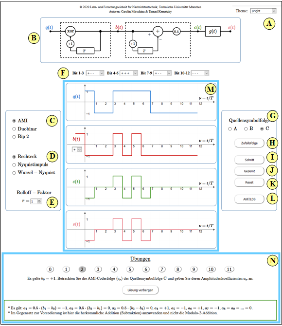
(B) Zugrundeliegendes Blockschaltbild
(C) Auswahl des Pseudoternörcodes:
AMI–Code, Duobinärcode, Bipolarcode 2. Ordnung
(D) Auswahl des Grundimpulses $g(t)$:
Rechteckimpuls, Nyquistimpuls, Wurzel–Nyquistimpuls
(E) Rolloff–Faktor (Frequenzbereich) für "Nyquist" und "Wurzel–Nyquist"
(F) Einstellung von $3 \cdot 4 = 12$ Bit der Quellensymbolfolge
(G) Auswahl einer drei voreingestellten Quellensymbolfolgen
(H) Zufällige binäre Quellensymbolfolge
( I ) Schrittweise Verdeutlichung der Pseudoternärcodierung
(J) Ergebnis der Pseudoternärcodierung: Signale $q(t)$, $b(t)$, $c(t)$, $s(t)$
(K) Löschen der Signalverläufe im Grafikbereich $\rm M$
(L) Skizzen für Autokorrelationsfunktion & Leistungsdichtespektrum
(M) Grafikbereich: Quellensignal $q(t)$, Signal $b(t)$ nach Vorcodierung,
Codersignal $c(t)$ mit Rechtecken, Sendesignal $s(t)$ gemäß $g(t)$
(N) Bereich für Übungen: Aufgabenauswahl, Fragen, Musterlösung
About the Authors
This interactive calculation tool was designed and implemented at the Institute for Communications Engineering at the Technical University of Munich.
- The first version was created in 2010 by Stefan Müller as part of his diploma thesis with “FlashMX – Actionscript” (Supervisor: Günter Söder).
- In 2020 the program was redesigned by Carolin Mirschina as part of her bachelor thesis (Supervisor: Tasnád Kernetzky ) via "HTML5".
- Last revision and English version 2021 by Carolin Mirschina in the context of a working student activity. Translation using DEEPL.com.
The conversion of this applet to HTML 5 was financially supported by "Studienzuschüsse" (Faculty EI of the TU Munich). We thank.
