Exercise 1.3Z: ISDN Bus System and Interfaces
From LNTwww
(Redirected from Aufgabe 1.3Z: Bussystem und Schnittstellen von ISDN)
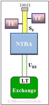
The graphic shows an ISDN transmission system. One recognizes:
- The network termination $\rm (NTBA)$ at the subscriber,
- the $\rm U_{\rm K0}$ interface as the connection between the NTBA and the local exchange $\rm (LE)$,
- the $\rm S_{0}$ bus, to which several terminal equipment $\rm (TE)$ of the subscribers can be connected.
On the $\rm U_{\rm K0}$ bus, two-wire transmission is used for economic reasons.
To decouple the receiver from its own transmitter, directional separation methods are required:
- The "fork circuit" is a bridge circuit, where an attempt is made to approximate the input impedance $Z_{\rm L}(f)$ of the copper two-wire line coupled via transformers as closely as possible by means of an artificial line replica $Z_{\rm N}(f)$.
- For narrowband signals, the resistance replica of $Z_{\rm L}(f)$ by $Z_{\rm N}(f)$ succeeds relatively well, so that the decoupling of transmitter and receiver is ensured by the fork circuit alone.
- For broadband signals, the "echo cancellation method" must also be used. Here, the transmitter emits test signals at regular intervals, measures the received signal and determines the echo impulse response from it.
- In normal operation, the echo canceller calculates the expected echo of its own transmitter depending on the message and subtracts this from the received signal in a transversal filter whose coefficients are set and re-adjusted by a powerful processor.
Note:
- The exercise belongs to the chapter "ISDN Basic Access".
- In particular, reference is made to the section "Directional separation method".
Questions
Solution
(1) The identifier "$0$" already indicates a basic rate interface.
- In the case of the primary rate multiplex connection, the interfaces are designated $\rm S_{\rm 2M}$ and $\rm U_{\rm K2}$,
- while the network termination equipment is designated $\rm NTPM$ ("Network Termination for Primary Rate Multiplex Access").
(2) Answer 1 is correct:
- Each NTBA is connected to the local exchange by a pair of wires. The identifier "K" in $\rm U_{\rm K0}$ indicates a copper line.
- Only in the case of a "primary rate interface" with $30$ B channels, one D channel and one synchronization channel a connection via optical fiber is possible.
- But even for this, copper lines are usually used.
(3) Solution 2 is correct:
- In the house connection area, ISDN uses four-wire transmission, with one copper twisted pair for each transmission direction.
(4) Solutions 1 and 3 are correct:
- A directional separation method is only required for two-wire transmission,
- whereby the simpler method is realized by means of a fork circuit in each NTBA.
(5) Solutions 1, 3 and 4 are correct:
- If the length is limited to $150$ meters, up to eight terminals can be connected at any point. This is referred to as a "short bus".
- An "extended bus" exists if the line length is up to $500$ meters.
- Here, up to four terminal equipment can be connected; these must be concentrated on the last $50$ meters before the terminating resistor $(100 \ \rm \Omega)$.
- In the case of a single connection, the line length can be increased to one kilometer ("long bus").
- Analog terminal equipment cannot be connected directly to the $\rm S_{0}$ bus, but only via a terminal adapter $\rm (TA)$.
