Exercise 3.4Z: Equivalent Convolution Codes?
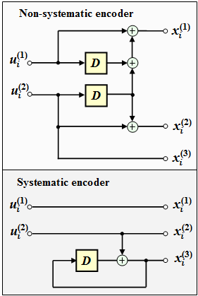
The top figure shows a convolutional encoder described by the following equations:
- $$x_i^{(1)} \hspace{-0.15cm} \ = \ \hspace{-0.15cm} u_{i}^{(1)} + u_{i-1}^{(1)}+ u_{i-1}^{(2)} \hspace{0.05cm},$$
- $$x_i^{(2)} \hspace{-0.15cm} \ = \ \hspace{-0.15cm} u_{i}^{(2)} + u_{i-1}^{(2)} \hspace{0.05cm},$$
- $$x_i^{(3)} \hspace{-0.15cm} \ = \ \hspace{-0.15cm} u_{i}^{(2)}\hspace{0.05cm}.$$
We are looking for the transfer function matrices
- $\mathbf{G}(D)$ of this non-systematic code, and
- $\mathbf{G}_{\rm sys}(D)$ of the equivalent systematic code.
The matrix $\mathbf{G}_{\rm sys}(D)$ is obtained in the following way:
- One splits off from the $k × n$ matrix $\mathbf{G}(D)$ in front a square matrix $\mathbf{T}(D)$ with $k$ rows and $k$ columns. The remainder is denoted by $\mathbf{Q}(D)$.
- Calculate the inverse matrix $\mathbf{T}^{-1}(D)$ of $\mathbf{T}(D)$. From this calculate the matrix for the equivalent systematic code:
- $${\boldsymbol{\rm G}}_{\rm sys}(D)= {\boldsymbol{\rm T}}^{-1}(D) \cdot {\boldsymbol{\rm G}}(D) \hspace{0.05cm}.$$
- Since $\mathbf{T}^{–1}(D) \cdot \mathbf{T}(D)$ yields the $k × k$ identity matrix $\mathbf{I}_k$, the transfer function matrix of the equivalent systematic code can be written in the desired form:
- $${\boldsymbol{\rm G}}_{\rm sys}(D) = \big [ \hspace{0.05cm} {\boldsymbol{\rm I}}_k\hspace{0.05cm} ; \hspace{0.1cm} {\boldsymbol{\rm P}}(D) \hspace{0.05cm}\big ] \hspace{0.5cm}{\rm with}\hspace{0.5cm} {\boldsymbol{\rm P}}(D)= {\boldsymbol{\rm T}}^{-1}(D) \cdot {\boldsymbol{\rm Q}}(D) \hspace{0.05cm}. \hspace{0.05cm}$$
- The circuit below will certainly generate a systematic code with the same parameters $k$ and $n$.
In subtask (5) it has to be clarified whether this is indeed the "equivalent systematic code". That is, whether in fact for the two circuits exactly the same quantity $\{ \hspace{0.1cm} \underline{x} \hspace{0.1cm}\}$ of code sequences results when all possible information sequences $\{ \hspace{0.1cm} \underline{u} \hspace{0.1cm} \}$ are taken into account.
Hints:
- This exercise belongs to the chapter "Algebraic and Polynomial Description".
- Reference is made in particular to the sections
Questions
Solution
- The memory order $\underline{m = 1}$ $($number of memory elements per input$)$.
- The influence length is equal to the sum of all memory elements ⇒ $\underline{\nu = 2}$.
(2) The information bit $u_i^{(1)}$ affects only the first output $x_i^{(1)}$, while $u_i^{(2)}$ is used for $x_i^{(2)}$ and $x_i^{(3)}$.
- Thus, for the zeroth "partial matrix" is obtained:
- $${ \boldsymbol{\rm G}}_0 = \begin{pmatrix} 1 & 0 & 0\\ 0 & 1 & 1 \end{pmatrix} \hspace{0.05cm}. $$
- The delayed inputs affect as follows:
- $u_{i–1}^{(1)}$ affects $x_i^{(1)}$,
- $u_{i–1}^{(2)}$ affects $x_i^{(1)}$ and $x_i^{(2)}$:
- Thus, the partial matrix $\mathbf{G}_1$ and the transfer function matrix $\mathbf{G}(D)$:
- $${ \boldsymbol{\rm G}}_1 = \begin{pmatrix} 1 & 0 & 0\\ 1 & 1 & 0 \end{pmatrix} \hspace{0.3cm}\Rightarrow \hspace{0.3cm} { \boldsymbol{\rm G}}(D) = { \boldsymbol{\rm G}}_0 + { \boldsymbol{\rm G}}_1 \cdot D = \begin{pmatrix} 1+D & 0 & 0\\ D & 1+D & 1 \end{pmatrix} \hspace{0.05cm}. $$
- Therefore the proposed solutions 1 and 3 are correct.
- Answer 2 cannot be correct, because no element with $D^2$ can occur in the transfer function matrix when $m = 1$.
- $\mathbf{G}(D)$ is moreover a $2 × 3$ matrix; there is no third row.
(3) Splitting $\mathbf{G}(D)$ gives the $2 × 2$ matrix.
- $${ \boldsymbol{\rm T}}(D) = \begin{pmatrix} 1+D & 0 \\ D & 1+D \end{pmatrix} \hspace{0.3cm}\Rightarrow \hspace{0.3cm}{\rm det}\hspace{0.1cm}{ \boldsymbol{\rm T}}(D) = (1+D) \cdot (1+D) = 1+D^2 $$
- $$\Rightarrow \hspace{0.3cm}{ \boldsymbol{\rm T}}^{-1}(D) = \frac{1}{1+D^2} \cdot \begin{pmatrix} 1+D & 0 \\ D & 1+D \end{pmatrix} \hspace{0.05cm}. $$
- The correct solution is solution 3. For control:
- $${ \boldsymbol{\rm T}}(D) \cdot { \boldsymbol{\rm T}}^{-1}(D) \hspace{-0.15cm} \ = \ \hspace{-0.15cm} \frac{1}{1+D^2} \cdot \begin{pmatrix} 1+D & 0 \\ D & 1+D \end{pmatrix} \cdot \begin{pmatrix} 1+D & 0 \\ D & 1+D \end{pmatrix} =$$
- $$ \ = \ \hspace{-0.15cm} ... \hspace{0.1cm}= \frac{1}{1+D^2} \cdot \begin{pmatrix} 1+D^2 & 0 \\ 0 & 1+D^2 \end{pmatrix} = \begin{pmatrix} 1 & 0 \\ 0 & 1 \end{pmatrix}\hspace{0.05cm}. $$
(4) According to the data sheet applies:
- $${ \boldsymbol{\rm P}}(D) \hspace{-0.15cm} \ = \ \hspace{-0.15cm} { \boldsymbol{\rm T}}^{-1}(D) \cdot { \boldsymbol{\rm Q}}(D) = \frac{1}{1+D^2} \cdot \begin{pmatrix} 1+D & 0 \\ D & 1+D \end{pmatrix} \cdot \begin{pmatrix} 0 \\ 1 \end{pmatrix} =$$
- $$\ = \ \hspace{-0.15cm} \frac{1}{1+D^2} \cdot \begin{pmatrix} (1+D)\cdot 0 + 0 \cdot 1 \\ D\cdot 0 + (1+D)\cdot 1 \end{pmatrix} = \frac{1}{1+D^2} \cdot \begin{pmatrix} 0 \\ 1+D \end{pmatrix} = \begin{pmatrix} 0 \\ 1/(1+D) \end{pmatrix} $$
- $$\Rightarrow \hspace{0.3cm} {\boldsymbol{\rm G}}_{\rm sys}(D) = \begin{pmatrix} 1 & 0 & 0\\ 0 & 1 & 1/(1+D) \end{pmatrix}\hspace{0.05cm}. $$
- The correct solution is therefore the proposals 1 and 3.
(5) Correct is YES. The lower circuit on the data sheet is identified by the equations $x_i^{(1)} = u_i^{(1)}$, $x_i^{(2)} = u_i^{(2)}$, and
- $$x_i^{(3)}= x_{i-1}^{(3)} + u_i^{(2)} \hspace{0.15cm} \circ\!\!-\!\!\!-^{\hspace{-0.25cm}D}\!\!\!-\!\!\bullet\hspace{0.15cm} X^{(3)}(D)= X^{(3)}(D) \cdot D +U^{(2)}(D)$$
- $$\Rightarrow \hspace{0.3cm} G(D) = \frac {X^{(3)}(D)}{U^{(2)}(D)} = \frac {1}{1+D} \hspace{0.05cm}.$$
- This corresponds exactly to the last element of $\mathbf{G}_{\rm sys}(D)$ from subtask (4).
