Exercise 4.2: UMTS Radio Channel Basics
From LNTwww
(Redirected from Aufgabe 4.2: Grundlegendes zum UMTS-Funkkanal)
UMTS also has quite a few effects leading to degradation that must be taken into account during system planning:
- ${\rm Interference}$: Since all users are simultaneously served in the same frequency band, each user is interfered by other users.
- ${\rm Path\:loss}$: The received power $P_{\rm E}$ of a radio signal decreases with distance $d$ by a factor $d^{- \gamma}$.
- ${\rm Multipath\:propagation}$: The signal reaches the mobile receiver not only through the direct path, but through several paths – differently attenuated and differently delayed.
- ${\rm Doppler\:effect}$: If transmitter and/or receiver move, frequency shifts can occur depending on speed and the direction $($Which angle? Towards each other? Away from each other?$)$.
In the book "Mobile Communications" these effects have already been discussed in detail. The diagrams convey only a few pieces of information regarding
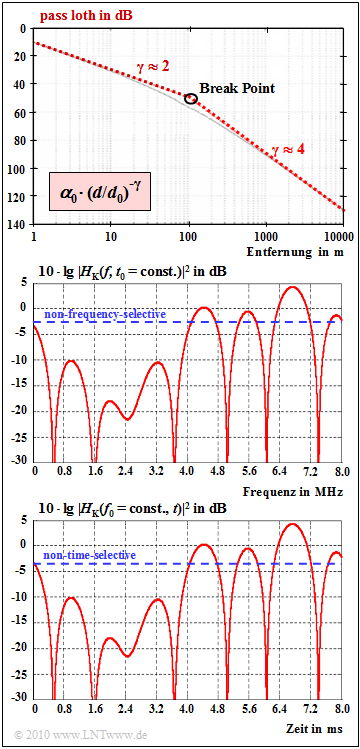
- Path loss: Path loss indicates the decrease in the received power with distance $d$ from the transmitter. Above the so-called "break point" applies approximately to the received power:
- $$\frac{P(d)}{P(d_0)} = \alpha_0 \cdot \left ( {d}/{d_0}\right )^{-4}.$$
- According to the upper graph $\alpha_{0} = 10^{-5}$ $($correspondingly $50 \ \rm dB)$ and $d_{0} = 100 \ \rm m$.
- Frequency-selective fading: The power transfer function $|H_{\rm K}(f)|^{2}$ at a given time according to the middle graph illustrates frequency-selective fading. The blue-dashed horizontal line, on the other hand, indicates non-frequency-selective fading.
- Such frequency-selective fading occurs when the coherence bandwidth $B_{\rm K}$ is much smaller than the signal bandwidth $B_{\rm S}$. Here, with the "delay spread" $T_{\rm V}$ ⇒ difference between the maximum and minimum delay times:
- $$B_{\rm K}\approx \frac{1}{T_{\rm V}}= \frac{1}{\tau_{\rm max}- \tau_{\rm min}}.$$
- Time-selective fading: The bottom graph shows the power transfer function $|H_{\rm K}(t)|^{2}$ for a fixed frequency $f_{0}$. The sketch is to be understood schematically, because for the time-selective fading considered here exactly the same course was chosen as in the middle diagram for the frequency-selective fading $($pure convenience of the author$)$.
- Here a so-called "Doppler spread" $B_{\rm D}$ arises, defined as the difference between the maximum and the minimum Doppler frequency. The inverse $T_{\rm D} = 1/B_{\rm D}$ is called "coherence time" or also "correlation duration". In UMTS, time-selective fading occurs whenever $T_{\rm D} \ll T_{\rm C}$ $($chip duration$)$.
Hints:
- This exercise belongs to the chapter "General Description of UMTS".
- Reference is made in particular to the sections "Properties of the UMTS radio channel" and "Frequency-selective and time-selective fading".
- For UMTS, the bandwidth: $B_{\rm S} = 5 \ \rm MHz$ and the chip duration: $T_{\rm C} \approx 0.26 \ \rm µ s$.
Questions
Solution
(1) According to the sketch, the breakpoint is at $d_{0} = 100 \ \rm m$.
- For $d ≤ d_{0}$, the path loss is equal to $\alpha_{0} \cdot (d/d_{0})^{-2}$. For $d = d_{0} = 100 \ \rm m$ holds:
- $${\rm path\ loss} = \alpha_0 = 10^{-5}\hspace{0.5cm}\Rightarrow\hspace{0.5cm}{50\,{\rm dB}}.$$
- Above $d_{0}$, the path loss is equal to $\alpha_{0} \cdot (d/d_{0})^{-4}$. Thus, at $5 \ \rm km$ distance, one obtains:
- $${\rm path\ loss} = 10^{-5}\cdot 50^{-4} = 1.6 \cdot 10^{-12}\hspace{0.5cm}\Rightarrow\hspace{0.5cm}\underline{118\,{\rm dB}}.$$
(2) Correct are the statements 1, 3, and 4:
- Frequency-selective fading is due to multipath reception. This means:
- Different frequency components are delayed and attenuated differently by the channel.
- This results in attenuation and phase distortion.
- Because $\tau_{\rm max} = 1 \ \rm µ s$ $($simplifying $\tau_{\rm min} = 0$ is set$)$ further results in
- $$B_{\rm K} = \frac{1}{\tau_{\rm max}- \tau_{\rm min}} = 1\,{\rm MHz}\ \ll \ B_{\rm S} \hspace{0.15cm}\underline {= 5\,{\rm MHz}}.$$
(3) Correct is statement 2.
- Statements 1 and 3, on the other hand, are valid for frequency-selective fading – see subtask (2).
