Exercise 3.7Z: Regenerator Field Length
By simulation, it was shown that there is approximately a linear relationship between the so-called "system efficiency" $\eta$ and the "characteristic cable attenuation" $a_*$ of a coaxial cable – both plotted in $\rm dB$ – if the characteristic cable attenuation is sufficiently large $(a_* ≥ 40 \ \rm dB)$:
- $$10 \cdot {\rm lg}\hspace{0.1cm}\eta \hspace{0.15cm} {\rm (in \hspace{0.15cm}dB)}= A + B \cdot a_{\star} \hspace{0.05cm}.$$
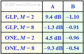
In the table, the empirically found coefficients $A$ and $B$ are given for four exemplary system variants:
- for the intersymbol interference binary system $(M = 2)$ with Gaussian low-pass filter $\rm (GLP)$, see chapter
"Error Probability with Intersymbol Interference",
- for the intersymbol interference octal system $(M = 8)$ with Gaussian low-pass filter $\rm (GLP)$, see chapter
"Intersymbol Interference for Multi-Level Transmission",
- for optimal ISI–free systems $\rm (ONE)$, see chapter "Linear Nyquist Equalization"; $M = 2$ and $M = 8$.
The larger the system efficiency $\eta$, the better a system is for a given value $a_*$ (and thus a fixed cable length).
For the calculation of the regenerator field length (distance between two repeaters), it should be noted:
- The worst-case error probability should not be larger than $10^{-10}$, which results in the minimum sink SNR:
- $$10 \cdot {\rm lg}\hspace{0.1cm}\rho_{\rm min} \approx 16.1\,{\rm dB} \hspace{0.05cm},$$
- The logarithmized ratio of transmit energy (per bit) and AWGN noise power density is about $100 \ \rm dB$, for example:
- $$s_0 = 3\,{\rm V},\hspace{0.2cm}R_{\rm B} = 1\,{\rm Gbit/s},\hspace{0.2cm}N_{\rm 0} = 9 \cdot 10^{-19}\,{\rm V^2/Hz}$$
- $$\Rightarrow \hspace{0.3cm}10 \cdot {\rm lg} \hspace{0.1cm}\frac{s_0^2 }{N_0 \cdot R_{\rm B}}= 10 \cdot {\rm lg} \hspace{0.1cm} \frac{9\,{\rm V^2} } {9 \cdot 10^{-19}\,{\rm V^2/Hz} \cdot 10^{-9}\,{\rm 1/s}} = 100\,{\rm dB} \hspace{0.05cm}.$$
- A standard coaxial cable with dimensions $2.6 \ \rm mm$ (inside) and $9.5 \ \rm mm$ (outside) is to be used, for which the following relationship is valid:
- $$a_{\star} = \frac{2.36\,{\rm dB} } {{\rm km} \cdot \sqrt{{\rm MHz}}} \cdot l \cdot \sqrt{{R_{\rm B}}/{2}} \hspace{0.05cm}.$$
- Here, $a_*$ denotes the characteristic attenuation at half the bit rate – in the example at $500 \ \rm MHz$ – and $l$ denotes the cable length.
Note: The exercise belongs to the chapter "Linear Nyquist Equalization".
Questions
Solution
- $$({\rm GLP},\hspace{0.1cm}M=2) \text{:}\hspace{0.3cm} 10 \cdot {\rm lg}\hspace{0.1cm}\eta = +9.4\,{\rm dB} -1.10 \cdot 40\,{\rm dB} = -34.6\,{\rm dB}\hspace{0.05cm},$$
- $$({\rm GLP},\hspace{0.1cm}M=8) \text{:}\hspace{0.3cm}10 \cdot {\rm lg}\hspace{0.1cm}\eta = -1.3\,{\rm dB} -0.91 \cdot 40\,{\rm dB} = -37.7\,{\rm dB}\hspace{0.05cm},$$
- $$({\rm ONE},\hspace{0.1cm}M=2) \text{:}\hspace{0.3cm}10 \cdot {\rm lg}\hspace{0.1cm}\eta = +4.5\,{\rm dB} -0.96 \cdot 40 \,{\rm dB}= -33.9\,{\rm dB}\hspace{0.05cm},$$
- $$({\rm ONE},\hspace{0.1cm}M=8) \text{:}\hspace{0.3cm} 10 \cdot {\rm lg}\hspace{0.1cm}\eta = -9.3\,{\rm dB} -0.54 \cdot 40\,{\rm dB} = -30.9\,{\rm dB}\hspace{0.05cm}.$$
From this it follows:
- The first statement is true because the system $({\rm ONE},\hspace{0.1cm} M = 8)$ is already best at $40 \ \rm dB$ cable attenuation and has the most favorable $\rm B$ coefficient.
- In contrast, the second statement is false because, for example, at $40 \ \rm dB$ cable attenuation, the octal $\rm GLP$ system is worse than the binary one.
(2) As a determination equation, we use here:
- $$-1.3\,{\rm dB} -0.91 \cdot a_{\star} = +4.5 \,{\rm dB}-0.96 \cdot a_{\star}\hspace{0.3cm} \Rightarrow \hspace{0.3cm} 0.05 \cdot a_{\star} = 5.8\,{\rm dB} \hspace{0.3cm}\Rightarrow \hspace{0.3cm}a_{\star,\hspace{0.05cm}{\rm limit}} \hspace{0.15cm}\underline {= 116\,{\rm dB}}\hspace{0.05cm}.$$
That is:
- Up to the characteristic cable attenuation $a_* = 116 \ \rm dB$ $($note: this is an unrealistically large value for currently realized systems$)$, the binary Nyquist system is superior to the system $({\rm GLP},\hspace{0.1cm} M = 8)$.
- Only for larger values than $a_{\rm *, \ limit} = 116 \ \rm dB$ does the advantage of the latter $(M = 8$ and thus significantly lower symbol rate$)$ outweigh the disadvantage $($octal decision and thus greater weight of intersymbol interference$)$.
(3) The sink SNR should be at least $16.1 \ \rm dB$, which means that it must be valid:
- $$10 \cdot {\rm lg}\hspace{0.1cm}\rho = 10 \cdot {\rm lg} \hspace{0.1cm}\frac{s_0^2 }{N_0 \cdot R_{\rm B}} + 10 \cdot {\rm lg}\hspace{0.1cm}\eta \hspace{0.3cm} \Rightarrow \hspace{0.3cm}10 \cdot {\rm lg}\hspace{0.1cm}\eta \ > \ 10 \cdot {\rm lg}\hspace{0.1cm}\rho_{\rm min} - 10 \cdot {\rm lg} \hspace{0.1cm}\frac{s_0^2 }{N_0 \cdot R_{\rm B}} = \ 16.1- 100\hspace{0.15cm}\underline {= -83.9\,{\rm dB} = 10 \cdot {\rm lg}\hspace{0.1cm}\eta_{\hspace{0.05cm} \rm min}}\hspace{0.05cm}.$$
(4) For the system considered here: $10 \cdot {\rm lg}\hspace{0.1cm}\eta = -9.3\,{\rm dB} -0.54 \cdot a_{\star}.$
- Thus, from the system efficiency condition ⇒ $10 \cdot {\rm lg} \, \eta > \hspace{0.1cm}–83.9 \ \rm dB $, the characteristic cable attenuation condition is:
- $$a_{\star} < \frac{-83.9\,{\rm dB} + 9.3\,{\rm dB}} {-0.54} \approx 138.1\,{\rm dB} \hspace{0.05cm}.$$
- With the given equation
- $$a_{\star} = \frac{2.36\,{\rm dB} } {{\rm km} \cdot \sqrt{{\rm MHz}}} \cdot l \cdot \sqrt{{R_{\rm B}}/{2}} \hspace{0.05cm}.$$
- thus the maximum cable length ("regenerator field length") can be specified:
- $$l_{\rm max} = \frac{138.1\,{\rm dB} } {2.36\,{\rm dB}/{\rm km} \cdot \sqrt{\rm MHz})\cdot \sqrt{500\,{\rm MHz}}} \hspace{0.15cm}\underline {\approx 2.62\, {\rm km}} \hspace{0.05cm}.$$
(5) Following the same procedure, but in a more compact notation, results in a smaller "regenerator field length" for this "worse" system:
- $$l_{\rm max} = \frac{-(83.9\,{\rm dB}+A)/B } {2.36\,{\rm dB}/{\rm km} \cdot \sqrt{500}} = \frac{+(83.9+9.4)/1.10 } {2.36\cdot \sqrt{500}}\hspace{0.1cm}{\rm km}\hspace{0.15cm}\underline {\approx 1.61\, {\rm km}} \hspace{0.05cm}.$$
