Contents
Optimization criterion of the Wiener-Kolmogorow filter
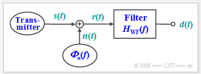
As another example of optimal filtering, we now consider the task of reconstructing as well as possible the shape of an useful signal $s(t)$ from the received signal $r(t)$, which is disturbed by additive noise $n(t)$, in terms of the "mean square error" (MSE):
- $${\rm{MSE}} = \mathop {\lim }\limits_{T_{\rm M} \to \infty } \frac{1}{{T_{\rm M} }}\int_{ - T_{\rm M} /2}^{+T_{\rm M} /2} {\left| {d(t) - s(t)} \right|^2 \, {\rm{d}}t} \mathop = \limits^! {\rm{Minimum}}.$$
The filter is named after its inventors $\text{Norbert Wiener}$ and $\text{Andrei Nikolajewitsch Kolmogorow}$. We denote the corresponding frequency response by $H_{\rm WF}(f).$
The following conditions apply to this optimization task:
- The signal $s(t)$ to be reconstructed is the result of a random process $\{s(t)\}$, of which only the statistical properties are known in the form of the power-spectral density ${\it Φ}_s(f)$.
- The noise signal $n(t)$ is given by the PSD ${\it Φ}_n(f)$. Correlations between the useful and noise signals are accounted for by the $\text{cross power-spectral density}$ ${\it Φ}_{sn}(f) = \hspace{0.1cm} –{ {\it Φ}_{ns} }^∗(f)$.
- The output signal of the sought filter is denoted by $d(t)$, which should differ as little as possible from $s(t)$ according to the MSE. $T_{\rm M}$ again denotes the measurement duration.
Let the signal $s(t)$ be mean-free $(m_s = 0)$ and power-limited. This means: The signal energy $E_s$ is infinite due to the infinite extension of the signal $s(t)$ and the signal power has a finite value:
- $$P_s = \mathop {\lim }\limits_{T_{\rm M} \to \infty } \frac{1}{{T_{\rm M} }}\int_{ - T_{\rm M} /2}^{+T_{\rm M} /2} |{s(t)|^2 \, {\rm{d}}t > 0.}$$
- A fundamental difference with the matched filter task is the stochastic and power-limited useful signal $s(t)$.
- Let us recall: In the matched filter, the signal $g(t)$ to be reconstructed was deterministic, limited in time and thus also energy-limited.
Result of the filter optimization
$\text{Here without proof:}$ The »transmission function of the optimal filter« can be determined by the so-called "Wiener-Hopf integral equation", and is:
- $$H_{\rm WF} (f) = \frac{{ {\it \Phi }_s (f) + {\it \Phi }_{ns} (f)} }{ { {\it \Phi }_s (f) + {\it \Phi }_{sn} (f) + {\it \Phi }_{ns} (f) + {\it \Phi }_n (f)}}.$$
- $\text{A. Kolmogorow}$ and $\text{N. Wiener}$ independently solved this optimization problem almost at the same time.
- The index "WF" stands for Wiener filter and unfortunately does not reveal the merits of Kolmogorov.
- The derivation of this result is not trivial and can be found for example in [Hän97][1].
The mathematical derivation of the equation is omitted. Rather, this filter shall be clarified and interpreted in the following on the basis of some special cases.
- If signal and disturbance are uncorrelated ⇒ ${\it Φ}_{sn}(f) = {\it Φ}_{ns}(f) = 0$, the above equation simplifies as follows:
- $$H_{\rm WF} (f) = \frac{{ {\it \Phi }_s (f) }}{{ {\it \Phi }_s (f) + {\it \Phi }_n (f) }} = \frac{1}{{1 + {\it \Phi }_n (f) / {\it \Phi }_s (f) }}.$$
- The filter then acts as a frequency-dependent divider, with the divider ratio determined by the power-spectral densities of the useful signal and the noise signal.
- The "passband" is predominantly at the frequencies where the useful signal has much larger components than the interference:
- $${\it Φ}_s(f) \gg {\it Φ}_n(f).$$
- The mean square error (MSE) between the filter output signal $d(t)$ and the input signal $s(t)$ is
- $${\rm MSE} = \int\limits_{ - \infty }^{ + \infty } {\frac{{ {\it \Phi }_s (f) \cdot {\it \Phi }_n (f)}}{{ {\it \Phi }_s(f) + {\it \Phi }_n (f)}}\,{\rm{d}}f = \int\limits_{ - \infty }^{ + \infty } {H_{\rm WF} (f) \cdot {\it \Phi }_n (f)}\, {\rm{d}}f.}$$
Interpretation of the Wiener filter
Now we will illustrate the Wiener-Kolmogorov filter with two examples.
$\text{Example 1:}$ To illustrate the Wiener filter, we consider as a limiting case a transmitted signal $s(t)$ with the power-spectral density ${\it Φ}_s(f) = P_{\rm S} · δ(f ± f_{\rm S}).$
- Thus, it is known that $s(t)$ is a harmonic oscillation with frequency $f_{\rm S}$.
- On the other hand, the amplitude and phase of the current sample function $s(t)$ are unknown.
With white noise ⇒ ${\it Φ}_n(f) = N_0/2$ the frequency response of the Wiener filter is thus:
- $$H_{\rm WF} (f) = \frac{1}{ {1 +({N_0 /2})/{\big[ P_{\rm S} \cdot\delta ( {f \pm f_{\rm S} } \big ]} })}.$$
- For all frequencies except $f = ±f_{\rm S}$, $H_{\rm WF}(f) = 0$ is obtained, since here the denominator becomes infinitely large.
- If we further consider that $δ(f = ±f_{\rm S})$ is infinitely large at the point $f = ±f_{\rm S}$, we further obtain $H_{\rm MF}(f = ±f_{\rm S} ) = 1. $
- Thus, the optimal filter is a band-pass around $f_{\rm S}$ with infinitesimally small bandwidth.
- The mean square error between the transmitted signal $s(t)$ and the filter output signal $d(t)$ is
- $${\rm{MSE} } = \int_{ - \infty }^{ + \infty } {H_{\rm WF} (f) \cdot {\it \Phi_n} (f) \,{\rm{d} }f = \mathop {\lim }\limits_{\varepsilon \hspace{0.03cm} {\rm > \hspace{0.03cm}0,}\;\;\varepsilon \hspace{0.03cm} \to \hspace{0.03cm}\rm 0 } }\hspace{0.1cm} \int_{f_{\rm S} - \varepsilon }^{f_{\rm S} + \varepsilon }\hspace{-0.3cm} {N_0 }\,\,{\rm{d} }f = 0.$$
- This infinitely narrow band-pass filter would allow complete regeneration of the harmonics in terms of amplitude and phase, given the assumptions made. Thus, regardless of the magnitude of the interference $(N_0)$, $d(t) = s(t)$ would apply.
- However, an infinitely narrow filter is not feasible. With finite bandwidth $Δf$, the mean square error is ${\rm MSE} = N_0 · Δf$.
This example has dealt with a special case where the best possible result $\rm MSE = 0$ would be possible, at least theoretically. The following example makes more realistic assumptions and gives the result $\rm MSE > 0$.
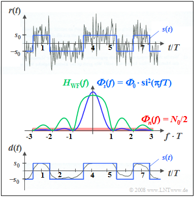
$\text{Example 2:}$ Now consider a stochastic rectangular binary signal $s(t)$, additively overlaid by white noise $n(t)$.
The diagram contains the following plots:
- At the top, the sum signal $r(t) = s(t) + n(t)$ is shown in gray for ${\it Φ}_0/N_0 = 5$, where ${\it Φ}_0$ denotes the energy of a single pulse and $N_0$ indicates the power density of the white noise. The useful signal $s(t)$ is drawn in blue.
- In the center of the figure, the power-spectral densities ${\it Φ}_s(f)$ and ${\it Φ}_n(f)$ are sketched in blue and red, respectively, and given in terms of formulas. The resulting frequency response $H_{\rm WF}(f)$ is drawn in green.
- The lower figure shows the output signal $d(t)$ of the Wiener filter as a gray curve in comparison to the transmitted signal $s(t)$ drawn in blue. Ideally, $d(t) = s(t)$ should be valid.
The bottom plot shows:
(1) The mean square error (MSE) is obtained by comparing the signals $d(t)$ and $s(t)$.
(2) Numerical evaluation showed $\rm MSE$ to be about $11\%$ of the useful power $P_{\rm S} $.
(3) The signal $d(t)$ predominantly lacks the higher frequency signal components (i.e. the jumps).
(4) These components are filtered out in favor of a better noise suppression of these frequencies.
Under these conditions, no other filter yields a smaller (mean square) error than the Wiener filter.
Its frequency response (green curve) is as follows:
- $$H_{\rm WF} (f) = \frac{1}{ {1 + ({N_0 /2})/( {\it \Phi}_0 \cdot {\rm si^2} ( \pi f T )})} \hspace{0.15cm} .$$
From the central plot you can see further:
- The DC signal transfer factor here results in $H_{\rm WF}(f = 0) = {\it Φ}_0/({\it Φ}_0 + N_0/2) = 10/11.$
- For multiples of the symbol repetition rate $1/T$, where the stochastic useful signal $s(t)$ has no spectral components, $H_{\rm WF}(f) = 0$.
- The more useful signal components are present at a certain frequency, the more permeable the Wiener filter is at this frequency.
Exercise for the chapter
Exercise 5.9: Minimization of the MSE
References
- ↑ Hänsler, E.: Statistische Signale: Grundlagen und Anwendungen. 2. Auflage. Berlin – Heidelberg: Springer, 1997.

