Difference between revisions of "Aufgaben:Exercise 3.7Z: Rectangular Signal with Echo"
| Line 67: | Line 67: | ||
[[File:P_ID532__Sig_Z_3_7_b_neu.png|right|frame|Convolution of square wave signal $s(t)$ and impulse response $h(t)$]] | [[File:P_ID532__Sig_Z_3_7_b_neu.png|right|frame|Convolution of square wave signal $s(t)$ and impulse response $h(t)$]] | ||
| − | '''(2)''' It holds | + | '''(2)''' It holds $r(t) = s(t) ∗ h(t)$. This convolution operation is most easily performed graphically: |
The values of the received signal are generally: | The values of the received signal are generally: | ||
| Line 82: | Line 82: | ||
| − | '''(3)''' Using a similar procedure as in '''(2)''' , a DC | + | '''(3)''' Using a similar procedure as in '''(2)''', a direct signal $\rm (DC)$ of $2\hspace{0.02cm}\text{ V}$ is obtained for $r(t)$ : |
| − | *The gaps in the signal $s(t)$ are completely filled by the echo $s(t - T/2)$. | + | *The gaps in the signal $s(t)$ are completely filled by the echo $s(t - T/2)$. |
| − | *This result can also be derived in the frequency domain. | + | *This result can also be derived in the frequency domain. The channel frequency response is with $\alpha = 1$ and $\tau = T/2$: |
| − | |||
:$$H( f ) = 1 + 1 \cdot {\rm{e}}^{ - {\rm{j\pi }}fT} = 1 + \cos ( {{\rm{\pi }}fT} ) - {\rm{j}} \cdot {\rm{sin}}( {{\rm{\pi }}fT} ).$$ | :$$H( f ) = 1 + 1 \cdot {\rm{e}}^{ - {\rm{j\pi }}fT} = 1 + \cos ( {{\rm{\pi }}fT} ) - {\rm{j}} \cdot {\rm{sin}}( {{\rm{\pi }}fT} ).$$ | ||
| − | *Apart from the DC component, the input signal ${s(t)}$ only has components at $f = f_0 = 1/T$, $f = 3 \cdot f_0$, $f = 5 \cdot f_0$ etc.. | + | *Apart from the DC component, the input signal ${s(t)}$ only has components at $f = f_0 = 1/T$, $f = 3 \cdot f_0$, $f = 5 \cdot f_0$, etc.. |
| − | *At these frequencies, however, both the real– and the imaginary part of ${H(f)}$ are equal to zero. | + | *At these frequencies, however, both the real– and the imaginary part of ${H(f)}$ are equal to zero. |
| − | *Thus, for the output spectrum with $A_0 = 1 \text{ V}$ and $H(f = 0) = 2$ we obtain: | + | *Thus, for the output spectrum with $A_0 = 1 \text{ V}$ and $H(f = 0) = 2$ we obtain: |
:$$R(f) = A_0 \cdot H(f = 0) \cdot \delta (f) = 2\;{\rm{V}} \cdot \delta (f).$$ | :$$R(f) = A_0 \cdot H(f = 0) \cdot \delta (f) = 2\;{\rm{V}} \cdot \delta (f).$$ | ||
| − | The inverse Fourier transformation thus also yields $r(t) \underline{= 2 \text{ V= const}}$. | + | The inverse Fourier transformation thus also yields $r(t) \underline{= 2 \text{ V= const}}$. |
{{ML-Fuß}} | {{ML-Fuß}} | ||
Revision as of 13:24, 28 April 2021
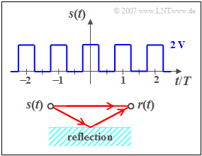
We consider a periodic rectangular signal $s(t)$ with the possible amplitude values $0\text{ V}$ and $2\text{ V}$ and the period duration $T_0 = T = 1 \text{ ms}$. At the jump points, e.g. at $t = T/4$, the signal value are $1\text{ V}$. The DC component $($i.e. the Fourier coefficient $A_0)$ of the signal is $1\text{ V}$, too.
Further applies:
- Due to symmetry (even function), all sine coefficients $B_n = 0$.
- The coefficients $A_n$ with even $n$ are also zero.
- For odd values of $n$, the following applies:
- $$A_n = ( { - 1} )^{\left( {n - 1} \right)/2} \cdot \frac{{4\;{\rm{V}}}}{{n \cdot {\rm{\pi }}}}.$$
The signal $s(t)$ reaches the receiver via two paths (see sketch below):
- Once on the direct path and secondly via a secondary path.
- The latter is characterised by the attenuation factor $\alpha$ and the transit time $\tau$ .
- Therefore, the following applies to the received signal:
- $$r(t) = s(t) + \alpha \cdot s( {t - \tau } ).$$
The frequency response of the channel is $H(f) = R(f)/S(f)$, the impulse response is denoted by $h(t)$ .
Hints:
- This exercise belongs to the chapter The Convolution Theorem and Operation.
- Important information can be found on the page Convolution of a function with a Dirac function.
Questions
Solution
- The impulse response is equal to the received signal $r(t)$, if a single Dirac impulse is present at the input at time $t = 0$ :
- $$h(t) = \delta (t) + \alpha \cdot \delta( {t - \tau } ).$$
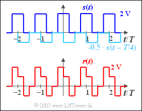
(2) It holds $r(t) = s(t) ∗ h(t)$. This convolution operation is most easily performed graphically:
The values of the received signal are generally:
- $0.00 < t/T < 0.25\text{:}\hspace{0.4cm} r(t) = +1\hspace{0.02cm}\text{ V}$,
- $0.25 < t/T < 0.50\text{:}\hspace{0.4cm} r(t) = -1 \hspace{0.02cm}\text{ V}$,
- $0.50 < t/T < 0.75\text{:}\hspace{0.4cm} r(t) = 0 \hspace{0.02cm}\text{ V}$,
- $0.75 < t/T < 1.00\text{:}\hspace{0.4cm} r(t) = +2 \hspace{0.02cm}\text{ V}$.
The values we are looking for are thus
- $$r(t = 0.2 \cdot T) \hspace{0.15cm}\underline{= +1 \hspace{0.02cm}\text{ V}},$$
- $$r(t = 0.3 · T) \hspace{0.15cm}\underline{= -1 \hspace{0.02cm}\text{ V}}.$$
(3) Using a similar procedure as in (2), a direct signal $\rm (DC)$ of $2\hspace{0.02cm}\text{ V}$ is obtained for $r(t)$ :
- The gaps in the signal $s(t)$ are completely filled by the echo $s(t - T/2)$.
- This result can also be derived in the frequency domain. The channel frequency response is with $\alpha = 1$ and $\tau = T/2$:
- $$H( f ) = 1 + 1 \cdot {\rm{e}}^{ - {\rm{j\pi }}fT} = 1 + \cos ( {{\rm{\pi }}fT} ) - {\rm{j}} \cdot {\rm{sin}}( {{\rm{\pi }}fT} ).$$
- Apart from the DC component, the input signal ${s(t)}$ only has components at $f = f_0 = 1/T$, $f = 3 \cdot f_0$, $f = 5 \cdot f_0$, etc..
- At these frequencies, however, both the real– and the imaginary part of ${H(f)}$ are equal to zero.
- Thus, for the output spectrum with $A_0 = 1 \text{ V}$ and $H(f = 0) = 2$ we obtain:
- $$R(f) = A_0 \cdot H(f = 0) \cdot \delta (f) = 2\;{\rm{V}} \cdot \delta (f).$$
The inverse Fourier transformation thus also yields $r(t) \underline{= 2 \text{ V= const}}$.

