Difference between revisions of "Aufgaben:Exercise 2.2: Modulation Depth"
m |
m |
||
| Line 7: | Line 7: | ||
:$$q(t) = A_{\rm N} \cdot \cos (2 \pi f_{\rm N} t),\hspace{0.2cm} f_{\rm N} = 4\,{\rm kHz}\hspace{0.05cm},$$ | :$$q(t) = A_{\rm N} \cdot \cos (2 \pi f_{\rm N} t),\hspace{0.2cm} f_{\rm N} = 4\,{\rm kHz}\hspace{0.05cm},$$ | ||
:$$ z(t) = \hspace{0.2cm}1 \hspace{0.15cm} \cdot \cos (2 \pi f_{\rm T} t),\hspace{0.2cm} f_{\rm T} = 50\,{\rm kHz}\hspace{0.05cm}.$$ | :$$ z(t) = \hspace{0.2cm}1 \hspace{0.15cm} \cdot \cos (2 \pi f_{\rm T} t),\hspace{0.2cm} f_{\rm T} = 50\,{\rm kHz}\hspace{0.05cm}.$$ | ||
| − | + | The modulated signal (transmitted signal) with the DC component added in the modulator is $A_{\rm T}$: | |
:$$s(t ) = A(t) \cdot z(t), \hspace{0.2cm} A(t) = q(t) + A_{\rm T}\hspace{0.05cm}.$$ | :$$s(t ) = A(t) \cdot z(t), \hspace{0.2cm} A(t) = q(t) + A_{\rm T}\hspace{0.05cm}.$$ | ||
In the graphs, the chosen normalization was: | In the graphs, the chosen normalization was: | ||
| Line 30: | Line 30: | ||
''Hints:'' | ''Hints:'' | ||
| − | * | + | *This exercise belongs to the chapter [[Modulation_Methods/Double-Sideband_Amplitude_Modulation|Double-Sideband Amplitude Modulation]]. |
| − | * | + | *Particular reference is made to the page [[Modulation_Methods/Double-Sideband_Amplitude_Modulation#Double-Sideband_Amplitude_Modulation_with_carrier|DSB-AM with carrier]]. |
| − | === | + | ===Questions=== |
<quiz display=simple> | <quiz display=simple> | ||
| − | { | + | {Determine the modulation depth for each of the signals $s_1(t)$, $s_2(t)$, $s_3(t)$ . |
|type="{}"} | |type="{}"} | ||
$m_1 \ = \ $ { 0.5 3% } | $m_1 \ = \ $ { 0.5 3% } | ||
| Line 45: | Line 45: | ||
$m_3 \ = \ $ { 3 3% } | $m_3 \ = \ $ { 3 3% } | ||
| − | { | + | {Which statements are true for the signal $s_4(t)$ ? |
|type="[]"} | |type="[]"} | ||
+ Es handelt sich um „ZSB–AM ohne Träger”. | + Es handelt sich um „ZSB–AM ohne Träger”. | ||
| Line 73: | Line 73: | ||
</quiz> | </quiz> | ||
| − | === | + | ===Solution=== |
{{ML-Kopf}} | {{ML-Kopf}} | ||
| − | '''(1)''' | + | '''(1)''' From the two equations |
:$$ A_{\rm max} = A_{\rm T}+A_{\rm N}=2\,\,{\rm V},\hspace{0.3cm} A_{\rm min} = A_{\rm T}-A_{\rm N}\hspace{0.05cm}$$ | :$$ A_{\rm max} = A_{\rm T}+A_{\rm N}=2\,\,{\rm V},\hspace{0.3cm} A_{\rm min} = A_{\rm T}-A_{\rm N}\hspace{0.05cm}$$ | ||
| − | + | directly follows: | |
:$$A_{\rm N} = (A_{\rm max} - A_{\rm min})/2,\hspace{0.3cm} | :$$A_{\rm N} = (A_{\rm max} - A_{\rm min})/2,\hspace{0.3cm} | ||
A_{\rm T} = (A_{\rm max} + A_{\rm min})/2\hspace{0.05cm}.$$ | A_{\rm T} = (A_{\rm max} + A_{\rm min})/2\hspace{0.05cm}.$$ | ||
| − | * | + | *Thus, the modulation depth is |
:$$m = \frac{A_{\rm max} - A_{\rm min}}{A_{\rm max} + A_{\rm min}}\hspace{0.05cm}.$$ | :$$m = \frac{A_{\rm max} - A_{\rm min}}{A_{\rm max} + A_{\rm min}}\hspace{0.05cm}.$$ | ||
| − | * | + | *With the given numerical values, one obtains: |
$$ m_1 = \frac{2\,{\rm V} - 0.667\,{\rm V}}{2\,{\rm V} + 0.667\,{\rm V}} \hspace{0.15cm}\underline {= 0.5}\hspace{0.05cm}, \hspace{0.5cm} m_2 = \frac{2\,{\rm V} - 0\,{\rm V}}{2\,{\rm V} + 0\,{\rm V}} \hspace{0.15cm}\underline {= 1.0}\hspace{0.05cm}, \hspace{0.5cm} | $$ m_1 = \frac{2\,{\rm V} - 0.667\,{\rm V}}{2\,{\rm V} + 0.667\,{\rm V}} \hspace{0.15cm}\underline {= 0.5}\hspace{0.05cm}, \hspace{0.5cm} m_2 = \frac{2\,{\rm V} - 0\,{\rm V}}{2\,{\rm V} + 0\,{\rm V}} \hspace{0.15cm}\underline {= 1.0}\hspace{0.05cm}, \hspace{0.5cm} | ||
m_3 = \frac{2\,{\rm V} -(-1\,{\rm V})}{2\,{\rm V} + (-1\,{\rm V})} \hspace{0.15cm}\underline{=3.0}\hspace{0.05cm}.$$ | m_3 = \frac{2\,{\rm V} -(-1\,{\rm V})}{2\,{\rm V} + (-1\,{\rm V})} \hspace{0.15cm}\underline{=3.0}\hspace{0.05cm}.$$ | ||
Revision as of 12:39, 24 November 2021
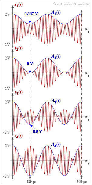
The graph shows DSB-amplitude modulated signals $s_1(t)$ to $s_4(t)$ with differing modulation depth $m$. Let message signal $q(t)$ and carrier signal $z(t)$ each be cosine:
- $$q(t) = A_{\rm N} \cdot \cos (2 \pi f_{\rm N} t),\hspace{0.2cm} f_{\rm N} = 4\,{\rm kHz}\hspace{0.05cm},$$
- $$ z(t) = \hspace{0.2cm}1 \hspace{0.15cm} \cdot \cos (2 \pi f_{\rm T} t),\hspace{0.2cm} f_{\rm T} = 50\,{\rm kHz}\hspace{0.05cm}.$$
The modulated signal (transmitted signal) with the DC component added in the modulator is $A_{\rm T}$:
- $$s(t ) = A(t) \cdot z(t), \hspace{0.2cm} A(t) = q(t) + A_{\rm T}\hspace{0.05cm}.$$
In the graphs, the chosen normalization was:
- $$A_{\rm T}+ A_{\rm N} = 2\,{\rm V}\hspace{0.05cm}.$$
- IIf the modulation depth is $m ≤ 1$, then $A(t)= q(t) + A_{\rm T}$ is equal to the envelope $a(t)$.
- In contrast, for a modulation depth $m > 1$:
- $$a(t ) = |A(t)|\hspace{0.05cm}.$$
- The cosine curve $A(t)$ varies between $A_{\rm max}$ and $A_{\rm min}$; because of normalization, $A_{\rm max} = 2 \ \rm V$ is always the case.
- The minimum values of $A(t)$ occur at half the period of the source signal $($i.e., for $t = 125 \ \rm µ s)$ :
- $$A_{\rm min} = q(T_0/2)+ A_{\rm T} = A_{\rm T}-A_{\rm N}.$$
- The numerical values are given in the graph.
Hints:
- This exercise belongs to the chapter Double-Sideband Amplitude Modulation.
- Particular reference is made to the page DSB-AM with carrier.
Questions
Solution
- $$ A_{\rm max} = A_{\rm T}+A_{\rm N}=2\,\,{\rm V},\hspace{0.3cm} A_{\rm min} = A_{\rm T}-A_{\rm N}\hspace{0.05cm}$$
directly follows:
- $$A_{\rm N} = (A_{\rm max} - A_{\rm min})/2,\hspace{0.3cm} A_{\rm T} = (A_{\rm max} + A_{\rm min})/2\hspace{0.05cm}.$$
- Thus, the modulation depth is
- $$m = \frac{A_{\rm max} - A_{\rm min}}{A_{\rm max} + A_{\rm min}}\hspace{0.05cm}.$$
- With the given numerical values, one obtains:
$$ m_1 = \frac{2\,{\rm V} - 0.667\,{\rm V}}{2\,{\rm V} + 0.667\,{\rm V}} \hspace{0.15cm}\underline {= 0.5}\hspace{0.05cm}, \hspace{0.5cm} m_2 = \frac{2\,{\rm V} - 0\,{\rm V}}{2\,{\rm V} + 0\,{\rm V}} \hspace{0.15cm}\underline {= 1.0}\hspace{0.05cm}, \hspace{0.5cm} m_3 = \frac{2\,{\rm V} -(-1\,{\rm V})}{2\,{\rm V} + (-1\,{\rm V})} \hspace{0.15cm}\underline{=3.0}\hspace{0.05cm}.$$
(2) Richtig sind die Aussagen 1 und 3:
- In diesem Fall ist $A_{\rm T} = 0$, das heißt, es liegt tatsächlich eine „ZSB–AM ohne Träger” vor.
- Der Modulationsgrad $m = A_{\rm N}/A_{\rm T}$ ist unendlich groß.
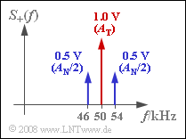
(3) Das Spektrum $S_+(f)$ setzt sich für jeden Modulationsgrad $m$ aus drei Diraclinien zusammen mit folgenden Gewichten:
- $A_{\rm T}$ $($bei $f = f_{\rm T})$,
- $m/2 · A_{\rm T}$ $($bei $f = f_{\rm T} ± f_{\rm N})$.
Für $m = 1$ ergeben sich die Gewichte entsprechend der Skizze:
- $S_+(f_{\rm T}) = 1\ \rm V$,
- $S_+(f_{\rm T} ± f_{\rm T}) = 0.5\ \rm V$.
(4) Die auf den Widerstand $1 \ Ω$ bezogene Leistung (Quadrat des Effektivwertes) einer harmonischen Schwingung mit der Amplitude $A_{\rm T} = 1 \ \rm V$ beträgt:
- $$P_{\rm T} ={A_{\rm T}^2}/{2} = 0.5\,{\rm V}^2 \hspace{0.05cm}.$$
- In gleicher Weise erhält man für die Leistungen des unteren und des oberen Seitenbandes:
- $$P_{\rm USB} = P_{\rm OSB} =({A_{\rm N}}/{2})^2/2 = 0.125\,{\rm V}^2 \hspace{0.05cm}.$$
- Das gesuchte Verhältnis ist somit für $m=1$:
- $${P_{\rm T}}/{P_{\rm S}}= \frac{P_{\rm T}}{P_{\rm USB} + P_{\rm T}+ P_{\rm OSB}}= \frac{0.5\,{\rm V}^2}{0.125\,{\rm V}^2 + 0.5\,{\rm V}^2+ 0.125\,{\rm V}^2}= 2/3\hspace{0.15cm}\underline { = 0.667}\hspace{0.05cm}.$$
(5) Mit den Diracgewichten $m/2 · A_{\rm T}$ der beiden Seitenbänder entsprechend der Teilaufgabe (3) erhält man:
- $${P_{\rm T}}/{P_{\rm S}}= \frac{A_{\rm T}^2/2}{A_{\rm T}^2/2 + 2 \cdot (m/2)^2 \cdot A_{\rm T}^2/2}= \frac{2}{2 + m^2}\hspace{0.05cm}.$$
- Dies führt zu den Zahlenwerten $8/9 = 0.889$ $($für $m = 0.5)$, $2/11 = 0.182$ $($für $m = 3)$ und $0$ $($für $m \to ∞$).
(6) Beide Aussagen treffen zu:
- Die Zusetzung des Trägers macht nur Sinn, um den einfacheren Hüllkurvendemodulator verwenden zu können. Dies geht nur für $m \le 1$.
- Ist dagegen der Modulationsgrad $m > 1$ und somit der Einsatz eines Synchrondemodulators erforderlich, sollte man aus energetischen Gründen auf den Träger (fast) ganz verzichten.
- Ebenso ist bei Anwendung eines Hüllkurvendemodulators aus energetischen Gründen ein möglichst großer Modulationsgrad $m < 1$ ⇒ $m \to 1$ anzustreben.
- Allerdings kann durch einen kleinen Restträger die Trägerrückgewinnung erleichtert werden, die beim Synchrondemodulator zur Frequenz– und Phasensynchronisation benötigt wird. Die zweite Aussage ist somit nur bedingt als richtig zu bewerten.

