Difference between revisions of "Aufgaben:Exercise 3.4: Simple Phase Modulator"
m (→Solution) |
m (→Solution) |
||
| Line 119: | Line 119: | ||
A simulation shows that by stopping the series after the third order term, we have made the error of over-estimating the distortion factor: | A simulation shows that by stopping the series after the third order term, we have made the error of over-estimating the distortion factor: | ||
| − | *The values obtained by simulation are $K ≈ 6%$ $($ | + | *The values obtained by simulation are $K ≈ 6%$ $($for $η = 1)$ and $K ≈ 2%$ $($for $η = 0.5)$. |
*Thus, the error increases more than proportionally with increasing $η$ . | *Thus, the error increases more than proportionally with increasing $η$ . | ||
Revision as of 19:35, 14 March 2022
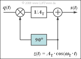
The adjacent circuit allows the approximate realization of a phase-modulated signal.
From the cosinusoidal carrier, $z(t)$ , the $90^\circ$ phase shifter forms a sinusoidal signal of the same frequency, such that the modulated signal can be written as:
- $$ s(t) = z(t) + q(t) \cdot \frac{z(t- T_0/4)}{A_{\rm T}} = A_{\rm T} \cdot \cos (\omega_{\rm T} \cdot t) + q(t) \cdot \sin (\omega_{\rm T} \cdot t) \hspace{0.05cm}.$$
The second term describes a "DSB–AM without carrier". Additionally, the carrier, phase-shifted by $90^\circ$ , is added. Thus, with a cosine source signal $q(t) = A_{\rm N} \cdot \cos (\omega_{\rm N} \cdot t)$ , we get:
- $$s(t) = A_{\rm T} \cdot \cos (\omega_{\rm T} \cdot t) + A_{\rm N} \cdot \cos (\omega_{\rm N} \cdot t) \cdot \sin (\omega_{\rm T} \cdot t) $$
- $$\Rightarrow \hspace{0.3cm}s(t) = A_{\rm T} \cdot \big[\cos (\omega_{\rm T} \cdot t) + \eta \cdot \cos (\omega_{\rm N} \cdot t) \cdot \sin (\omega_{\rm T} \cdot t) \big] \hspace{0.05cm}.$$
We refer to the ratio $η = A_{\rm N}/A_{\rm T}$ as the modulation index; in the following, the carrier amplitude is set to $A_{\rm T} = 1$ for simplicity.
- In contrast to ideal phase modulation the modulation index $η$ and the phase deviation $ϕ_{\rm max}$ may differ in this "approximate phase modulation".
- Additionally, we can see that the envelope $a(t) ≠ 1$ . This means that an unwanted amplitude modulation is superimposed on the phase modulation.
From the representation of the equivalent low-pass signal $s_{\rm TP}(t)$ in the complex plane (locus curve), the following are to be calculated in this task:
- the envelope $a(t)$ and
- the phase function $ϕ(t)$.
Then, you are to analyse the distortions arising when an ideal PM demodulator, which sets the sink signal $v(t)$ proportional to the phase $ϕ(t)$ , is used on the receiving side of this nonideal PM modulator.
Hints:
- This exercise belongs to the chapter Phase Modulation.
- Particular reference is made to the page Equivalent low-pass signal in phase modulation.
- You can use the following equations to approximate the distortion factor:
- $$\arctan(\gamma) \approx \gamma - {\gamma^3}/{3} \hspace{0.05cm}, \hspace{0.3cm} \cos^3(\gamma) ={3}/{4} \cdot \cos(\gamma) +{1}/{4} \cdot \cos(3 \cdot \gamma) \hspace{0.05cm}.$$
Questions
Solution
(1) Answer 3 is correct:
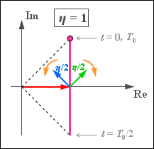
- The equivalent low-pass signal is::$$s_{\rm TP}(t) = A_{\rm T} \cdot \left ( 1 + {\rm j}\cdot \frac {\eta}{2}\cdot \left ({\rm e}^{\hspace{0.05cm}{\rm j} \hspace{0.05cm}\cdot \hspace{0.05cm}\omega_{\rm N} \hspace{0.05cm}\cdot \hspace{0.05cm} t} + {\rm e}^{\hspace{0.05cm}{-\rm j} \hspace{0.05cm}\cdot \hspace{0.05cm}\omega_{\rm N} \hspace{0.05cm}\cdot \hspace{0.05cm} t}\right) \right) = A_{\rm T} \cdot \big ( 1 + {\rm j}\cdot {\eta}\cdot \cos (\omega_{\rm N} \cdot t) \big)\hspace{0.05cm}.$$
- The graph illustrates that the locus curve $s_{\rm TP}(t)$ is now a a vertical straight line in contrast to the ideal PM (circular arc) and DSB–AM (horizontal straight line).
- In the following, we set $A_{\rm T} = 1$ .
(2) The envelope is obtained from the time-dependent pointer length as
- $$a(t) = \sqrt{1 + \eta^2 \cdot \cos^2 (\omega_{\rm N} \cdot t)} \hspace{0.3cm} \Rightarrow \hspace{0.3cm}a_{\rm min} \hspace{0.15cm}\underline { = 1}, \hspace{0.3cm}a_{\rm max} = \sqrt{1 + \eta^2 }\hspace{0.05cm}.$$
- For $η = 1$ the maximum value becomes $a_{\rm max} = \sqrt{2}\hspace{0.15cm}\underline { ≈ 1.414}$.
(3) The phase function of this simple phase demodulator is given by:
- $$\phi(t) = \arctan \frac{{\rm Im}[s_{\rm TP}(t)]}{{\rm Re}[s_{\rm TP}(t)]} = \arctan (\eta \cdot \cos (\omega_{\rm N} \cdot t)) \hspace{0.05cm}.$$
- The maximum value occurs at time $t = 0$ , for example, and is $ϕ_{\rm max} = \arctan(η)$.
- When $η = 1$ , one obtains $ϕ_{\rm max}\hspace{0.15cm}\underline { = 45^\circ}$ $($to compare: for ideal PM $57.3^\circ)$,
- When $η = 0.5$ one gets $ϕ_{\rm max}\hspace{0.15cm}\underline { \approx 26.6^\circ}$ $($for ideal PM $28.7^\circ)$.
(4) Answer 3 is correct:
- It is not true that: $\arctan\big [η · \cos(γ)\big ] = η · \cos(γ)$.
- This means that the sink signal is not cosine, in contrast to the source signal.
- This points to nonlinear distortions.
(5) Using $γ = η · \cos(ω_N · t)$ and $\arctan(γ) ≈ γ – γ^3/3$ , we get:
- $$ \phi(t) = \eta \cdot \cos (\omega_{\rm N} \cdot t) - \frac{\eta^3}{3}\cdot \cos^3 (\omega_{\rm N} \cdot t))= \eta \cdot \cos (\omega_{\rm N} \cdot t) - \frac{\eta^3}{3}\cdot \left [ {3}/{4}\cdot \cos (\omega_{\rm N} \cdot t) + {1}/{4}\cdot \cos (3 \omega_{\rm N} \cdot t)\right ] $$
- $$\Rightarrow \hspace{0.3cm} \phi(t) = \left(\eta - {\eta^3}/{4} \right) \cdot \cos (\omega_{\rm N} \cdot t) - {\eta^3}/{12}\cdot \cos (3\omega_{\rm N} \cdot t) \hspace{0.05cm}.$$
- This means: using the given series expansion (where 5th and higher order terms are ignored), only the third-order harmonic distortion is non-zero. Thus:
- $$K = K_3 = \frac{\eta^3/12}{\eta-\eta^3/4}= \frac{1}{12/\eta^2 -3} \hspace{0.05cm}.$$
- When $η = 1$ the numerical value is $K = 1/9 \hspace{0.15cm}\underline { ≈ 11.1\%}$.
- When $η = 0.5$ the distortion factor is $K = 1/45 \hspace{0.15cm}\underline {≈ 2.2\%}$.
A simulation shows that by stopping the series after the third order term, we have made the error of over-estimating the distortion factor:
- The values obtained by simulation are $K ≈ 6%$ $($for $η = 1)$ and $K ≈ 2%$ $($for $η = 0.5)$.
- Thus, the error increases more than proportionally with increasing $η$ .

