Difference between revisions of "Aufgaben:Exercise 4.14: Phase Progression of the MSK"
m |
m |
||
| Line 4: | Line 4: | ||
[[File:P_ID1740__Mod_A_4_13.png|right|frame|Source signal and low-pass signals <br>in both branches of the MSK]] | [[File:P_ID1740__Mod_A_4_13.png|right|frame|Source signal and low-pass signals <br>in both branches of the MSK]] | ||
| − | + | One possible implementation of ''Minimum Shift Keying'' $\rm (MSK)$ is offered by $\rm Offset–QPSK$, as shown in the [[Modulation_Methods/Nonlinear_Digital_Modulation#Realizing_MSK_as_Offset.E2.80.93QPSK|block diagram]] in the theory section. | |
| − | * | + | *For this, a recoding of the source symbols $q_k ∈ \{+1, –1\}$ into the similarly binary amplitude coefficients $a_k ∈ \{+1, –1\}$ must first be undertaken. |
| − | * | + | *This recoding is discussed in detail in [[Aufgaben:Exercise_4.14Z:_Offset_QPSK_vs._MSK|Exercise 4.14Z]] . |
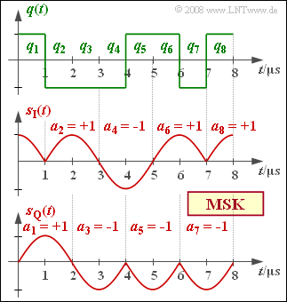
| − | + | The graph shows the two equivalent low-pass signals $s_{\rm I}(t)$ nd $s_{\rm Q}(t)$ in the two branches below, which are obtained for the inphase and quadrature branches after recoding $a_k = (-1)^{k+1} \cdot a_{k-1} \cdot q_k $ from the source signal $q(t)$ sketched above. Considered here is the MSK fundamental pulse, | |
:$$ g_{\rm MSK}(t) = \left\{ \begin{array}{l} \cos \big ({\pi \hspace{0.05cm} t}/({2 \hspace{0.05cm} T})\big ) \\ 0 \\ \end{array} \right.\quad \begin{array}{*{5}c}{\rm{f\ddot{u}r}} \\{\rm{f\ddot{u}r}} \\ \end{array}\begin{array}{*{10}c} -T \le t \le +T \hspace{0.05cm}, \\ {\rm sonst}\hspace{0.05cm}. \\ \end{array}$$ | :$$ g_{\rm MSK}(t) = \left\{ \begin{array}{l} \cos \big ({\pi \hspace{0.05cm} t}/({2 \hspace{0.05cm} T})\big ) \\ 0 \\ \end{array} \right.\quad \begin{array}{*{5}c}{\rm{f\ddot{u}r}} \\{\rm{f\ddot{u}r}} \\ \end{array}\begin{array}{*{10}c} -T \le t \le +T \hspace{0.05cm}, \\ {\rm sonst}\hspace{0.05cm}. \\ \end{array}$$ | ||
| − | + | This is normalized to $1$ , as are the signals $s_{\rm I}(t)$ and $s_{\rm Q}(t)$ . | |
| − | + | In keeping with the chapter [[Signal_Representation/Equivalent_Low_Pass_Signal_and_Its_Spectral_Function|Equivalent Low-Pass Signal and its Spectral Function]] in the book "Signal Representation", the equivalent low-pass signal is: | |
:$$ s_{\rm TP}(t) = s_{\rm I}(t) + {\rm j} \cdot s_{\rm Q}(t) = |s_{\rm TP}(t)| \cdot {\rm e}^{\hspace{0.05cm}{\rm j} \hspace{0.05cm} \cdot \hspace{0.05cm}\phi(t)}\hspace{0.05cm},$$ | :$$ s_{\rm TP}(t) = s_{\rm I}(t) + {\rm j} \cdot s_{\rm Q}(t) = |s_{\rm TP}(t)| \cdot {\rm e}^{\hspace{0.05cm}{\rm j} \hspace{0.05cm} \cdot \hspace{0.05cm}\phi(t)}\hspace{0.05cm},$$ | ||
| − | * | + | *with magnitude |
:$$|s_{\rm TP}(t)| = \sqrt{s_{\rm I}^2(t) + s_{\rm Q}^2(t)} $$ | :$$|s_{\rm TP}(t)| = \sqrt{s_{\rm I}^2(t) + s_{\rm Q}^2(t)} $$ | ||
| − | * | + | *and phase |
:$$ \phi(t) = {\rm arc} \hspace{0.15cm}s_{\rm TP}(t) = {\rm arctan}\hspace{0.1cm} \frac{s_{\rm Q}(t)}{s_{\rm I}(t)} \hspace{0.05cm}.$$ | :$$ \phi(t) = {\rm arc} \hspace{0.15cm}s_{\rm TP}(t) = {\rm arctan}\hspace{0.1cm} \frac{s_{\rm Q}(t)}{s_{\rm I}(t)} \hspace{0.05cm}.$$ | ||
| − | + | The physical MSK transmitted signal is then given by | |
:$$ s(t) = |s_{\rm TP}(t)| \cdot \cos (2 \pi \cdot f_{\rm T} \cdot t + \phi(t)) \hspace{0.05cm}.$$ | :$$ s(t) = |s_{\rm TP}(t)| \cdot \cos (2 \pi \cdot f_{\rm T} \cdot t + \phi(t)) \hspace{0.05cm}.$$ | ||
Revision as of 12:21, 21 March 2022
One possible implementation of Minimum Shift Keying $\rm (MSK)$ is offered by $\rm Offset–QPSK$, as shown in the block diagram in the theory section.
- For this, a recoding of the source symbols $q_k ∈ \{+1, –1\}$ into the similarly binary amplitude coefficients $a_k ∈ \{+1, –1\}$ must first be undertaken.
- This recoding is discussed in detail in Exercise 4.14Z .
The graph shows the two equivalent low-pass signals $s_{\rm I}(t)$ nd $s_{\rm Q}(t)$ in the two branches below, which are obtained for the inphase and quadrature branches after recoding $a_k = (-1)^{k+1} \cdot a_{k-1} \cdot q_k $ from the source signal $q(t)$ sketched above. Considered here is the MSK fundamental pulse,
- $$ g_{\rm MSK}(t) = \left\{ \begin{array}{l} \cos \big ({\pi \hspace{0.05cm} t}/({2 \hspace{0.05cm} T})\big ) \\ 0 \\ \end{array} \right.\quad \begin{array}{*{5}c}{\rm{f\ddot{u}r}} \\{\rm{f\ddot{u}r}} \\ \end{array}\begin{array}{*{10}c} -T \le t \le +T \hspace{0.05cm}, \\ {\rm sonst}\hspace{0.05cm}. \\ \end{array}$$
This is normalized to $1$ , as are the signals $s_{\rm I}(t)$ and $s_{\rm Q}(t)$ .
In keeping with the chapter Equivalent Low-Pass Signal and its Spectral Function in the book "Signal Representation", the equivalent low-pass signal is:
- $$ s_{\rm TP}(t) = s_{\rm I}(t) + {\rm j} \cdot s_{\rm Q}(t) = |s_{\rm TP}(t)| \cdot {\rm e}^{\hspace{0.05cm}{\rm j} \hspace{0.05cm} \cdot \hspace{0.05cm}\phi(t)}\hspace{0.05cm},$$
- with magnitude
- $$|s_{\rm TP}(t)| = \sqrt{s_{\rm I}^2(t) + s_{\rm Q}^2(t)} $$
- and phase
- $$ \phi(t) = {\rm arc} \hspace{0.15cm}s_{\rm TP}(t) = {\rm arctan}\hspace{0.1cm} \frac{s_{\rm Q}(t)}{s_{\rm I}(t)} \hspace{0.05cm}.$$
The physical MSK transmitted signal is then given by
- $$ s(t) = |s_{\rm TP}(t)| \cdot \cos (2 \pi \cdot f_{\rm T} \cdot t + \phi(t)) \hspace{0.05cm}.$$
Hints:
- This exercise belongs to the chapter Nonlinear Digital Modulation.
- Particular reference is made to the section Realizing MSK as Offset–QPSK.
- Assume $ϕ(t = 0) = ϕ_0 = 0$ .
Questions
Solution
- Beispielsweise gilt im Bereich $0 ≤ t ≤ T$, wenn man berücksichtigt, dass $a_0^2 = a_1^2 = 1$ ist:
- $$ |s_{\rm TP}(t)| = \sqrt{a_0^2 \cdot \cos^2 (\frac{\pi \cdot t}{2 \cdot T}) + a_1^2 \cdot \sin^2 (\frac{\pi \cdot t}{2 \cdot T})} = 1 \hspace{0.05cm}.$$
- Richtig ist damit die Aussage 2, während die Aussage 1 falsch.
- Dieses Ergebnis gilt für jedes Wertepaar $a_0 ∈ \{+1, \ –1\}$ und $a_1 ∈ \{+1, \ –1\}$.
- Daraus kann weiter geschlossen werden, dass die Hüllkurve unabhängig von der gesendeten Folge ist.
(2) Mit der angegebenen Gleichung gilt:
- $$\phi(t) = {\rm arctan}\hspace{0.1cm} \frac{s_{\rm Q}(t)}{s_{\rm I}(t)} = {\rm arctan}\hspace{0.1cm} \frac{a_1 \cdot \sin (\frac{\pi \cdot t}{2 \cdot T})}{a_0 \cdot \cos (\frac{\pi \cdot t}{2 \cdot T})}= {\rm arctan}\hspace{0.1cm}\left [ \frac{a_1}{a_0}\cdot \tan \hspace{0.1cm}(\frac{\pi \cdot t}{2 \cdot T})\right ] \hspace{0.05cm}.$$
- Der Quotient $a_1/a_0$ ist stets $+1$ oder $-1$. Damit kann dieser Quotient vorgezogen werden und man erhält:
- $$\phi(t) = \frac{a_1}{a_0}\cdot {\rm arctan}\hspace{0.1cm}\left [ \tan \hspace{0.1cm}(\frac{\pi \cdot t}{2 \cdot T})\right ]= \frac{a_1}{a_0}\cdot \frac{\pi \cdot t}{2 \cdot T} \hspace{0.05cm}.$$
- Durch die Anfangsphase $ϕ_0 = 0$ können Mehrdeutigkeiten ausgeschlossen werden. Insbesondere gilt mit $a_0 = a_1 = +1$:
- $$\phi(t = T/2 = 0.5\,{\rm µ s}) = {\pi}/{4}\hspace{0.15cm}\underline { = +45^\circ},\hspace{0.2cm}\phi(t = T= 1\,{\rm µ s}) = {\pi}/{2}\hspace{0.15cm}\underline {= +90^\circ} \hspace{0.05cm}.$$
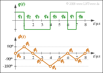
(3) Am einfachsten löst man diese Aufgabe unter Zuhilfenahme des Einheitskreises:
- $$ {\rm Re} = s_{\rm I}(2T) = +1, \hspace{0.2cm} {\rm Im} = s_{\rm Q}(2T) = 0 \hspace{0.3cm} \Rightarrow \hspace{0.3cm}\phi(t = 2T= 2\,{\rm µ s}) \hspace{0.15cm}\underline {= 0^\circ},$$
- $$ {\rm Re} = s_{\rm I}(3T) = 0, \hspace{0.2cm} {\rm Im} = s_{\rm Q}(3T) = -1 \hspace{0.3cm} \Rightarrow \hspace{0.3cm}\phi(t = 3T= 3\,{\rm µ s}) \hspace{0.15cm}\underline {= -90^\circ},$$
- $${\rm Re} = s_{\rm I}(4T) = -1, \hspace{0.2cm} {\rm Im} = s_{\rm Q}(4T) = 0 \hspace{0.3cm} \Rightarrow \hspace{0.3cm}\phi(t = 4T= 4\,{\rm µ s})= \pm 180^\circ \hspace{0.05cm}.$$
- Aus der unteren Skizze erkennt man, dass $\phi(t = 4T= 4\,{\rm µ s})\hspace{0.15cm}\underline { = - 180^\circ}\hspace{0.05cm}$ richtig ist.
(4) Die Grafik zeigt die MSK–Phase $ϕ(t)$ zusammen mit dem Quellensignal $q(t)$. Man erkennt:
- Beim Symbol $a_\nu =+1$ steigt die Phase innerhalb der Symboldauer $T$ linear um $90^\circ \ (π/2)$ an.
- Beim Symbol $a_\nu =-1$ fällt die Phase innerhalb der Symboldauer $T$ linear um $90^\circ \ (π/2)$ ab.
- Die weiteren Phasenwerte sind somit:
- $$\phi(5T) \hspace{0.15cm}\underline { = -90^\circ},\hspace{0.2cm}\phi(t = 6T) \hspace{0.15cm}\underline {= 0^\circ} \hspace{0.05cm}.$$
- $$ \phi(7T)\hspace{0.15cm}\underline { = -90^\circ},\hspace{0.2cm} \phi(t = 8T) \hspace{0.15cm}\underline {= 0^\circ} \hspace{0.05cm}.$$

