Difference between revisions of "Examples of Communication Systems/ISDN Primary Multiplex Connection"
m (Text replacement - "[[Beispiele_von_Nachrichtensystemen" to "[[Examples_of_Communication_Systems") |
|||
| (19 intermediate revisions by 4 users not shown) | |||
| Line 7: | Line 7: | ||
{{BlaueBox|TEXT= | {{BlaueBox|TEXT= | ||
| − | $\text{ | + | $\text{Preliminary remark:}$ Again, we would like to point out that the content of this chapter no longer fully reflects the current state of the art $($2018$)$. Therefore, consider the following text as a historical treatise, even if parts of it are still relevant in practice today.}} |
| − | == | + | == General description == |
<br> | <br> | ||
| − | + | First of all, it should be explained why an ISDN rate interface is $($or rather was$)$ needed. This was only offered as a '''system connection''' $($"point-to-point"$)$. This means that only one device could be connected to the network termination: One speaks of a "telecommunications system", abbreviated to "'''TC system'''" in the following. | |
| − | + | There were many reasons for using a system connection: | |
| − | + | # Companies, government agencies or hospitals often need a central number and a block of extension numbers. | |
| − | + | # Most often, the extension number of the central office is "0". | |
| − | + | # The central call number has $3$ to $5$ digits, an extension number thereafter has "2" to "5" digits. This allows direct dialing of a call partner from the outside. | |
| + | # Telephone calls between employees – i.e., an internal connection – should be free of charge. | ||
{{GraueBox|TEXT= | {{GraueBox|TEXT= | ||
| − | $\text{ | + | $\text{Example 1:}$ |
| − | + | Let's consider a company in Munich whose head office can be reached from outside via "089/4711 - 0" and internally with "0". Employee $X$ can be reached from outside at a charge by dialing extension "089/4711 - 432" and internally without charge by dialing "432".}} | |
| − | [[File: | + | Larger companies usually work with a '''primary rate interface''' $\rm (PRI)$, to which the telecommunications or data processing equipment is connected by a four-wire line. The primary rate interface according to the adjacent diagram offers: |
| + | [[File:EN_Bei_T_1_3_S1.png|right|frame|ISDN primary rate interface]] | ||
| − | + | *$30$ full-duplex basic channels with $\text{64 kbit/s}$ each, | |
| − | + | *one signaling channel $($"data channel"$)$ with $\text{64 kbit/s}$, | |
| − | * | + | |
| − | + | *one synchronization channel (also with $\text{64 kbit/s})$, and accordingly | |
| − | * | + | |
| − | * | + | *a '''gross data rate''' of $32 · 64 \hspace{0.15cm}\underline{ = 2048 \ \rm kbit/s}$. |
<br clear=all> | <br clear=all> | ||
| − | + | It follows some general information about the primary rate interface: | |
| − | + | # The $30$ user channels are implemented with the "PCM-30" multiplex system. In contrast to the basic rate interface, only a point-to-point connection is possible here. This means that a second system cannot be connected to the same line as with a bus. | |
| − | + | # The telecommunications system is connected to the local exchange via the network termination equipment $($"'''N'''etwork '''T'''ermination for '''P'''rimary Rate '''M'''ultiplex '''A'''ccess" ⇒ "$\rm NTPM$"$)$. This connection is four-wire ⇒ both transmission directions are separated. Thus, no direction separation procedures $($fork circuit, echo cancellation, etc.$)$ are required in the NTPM and in the local exchange. | |
| − | + | # The [[Examples_of_Communication_Systems/ISDN_Basic_Access#Some_explanations_of_terms|"reference point"]] $\rm U$ between the network termination and the local exchange is designated $\rm U_{K2}$ in the case of a primary multiplex connection if a copper cable $\rm (K)$ is used; the $\rm (2)$ stands for the transmission rate of $\text{2 Mbit/s}$. In the case of a fiber optic connection, this point is called $\rm U_{G2}$. | |
| − | + | # Accordingly, the connection between the network termination and the TC system is generally referred to as the "$\rm S_{2M}$" interface. Technically, however, there is not much difference between the "$\rm U_{K2}$" and the "$\rm S_{2M}$" interfaces. | |
| − | |||
| − | == | + | ==Frame structure of S<sub>2M</sub> and U<sub>K2</sub> interface== |
<br> | <br> | ||
| − | + | The $\rm S_{2M}$ interface represents the connection between the telecommunications system and the network termination $\rm (NTPM)$, which is implemented with two copper pairs. Since only point-to-point operation is possible here, the $\rm S_{2M}$ interface is not designed as a bus like the $\rm S_{0}$ interface in the basic connection, and therefore no collision detection method is required here. | |
| + | |||
| + | [[File:EN_Bei_T_1_3_S2.png|right|frame|Frame structure of the $\rm S_{2M}$ interface]] | ||
| + | The graphic shows the frame structure of the $\rm S_{2M}$ interface. It can be seen: | ||
| − | + | *In time division multiplex, a TDMA frame is transmitted every $125\ \rm µs$. However, each of the $32$ channels occupies the TDMA frame only for the duration of $125\ \rm µs/32 = 3.906 \ \rm µs$. | |
| − | + | *Eight bits are transmitted per channel and TDMA frame; the bit duration is | |
| − | + | :$$T_\text{B} = 3.906 \ \rm µs/8 = 0.488 \ \rm µs.$$ | |
| − | + | *The reciprocal of this is the gross data rate | |
| − | * | + | :$$R_\text{B} \hspace{0.15cm}\underline{= 2.048 \ \rm Mbit/s}.$$ |
| − | + | *The channels '''1''' to '''15''' and '''17''' to '''31''' represent the bearer ($\rm B)$ channels, all of which are operated independently of each other at $64 \ \rm kbit/s$. | |
| + | *The data channel '''16''' $($marked red in the graph$)$ provides control of these user channels and the entire telephone system. | ||
| − | + | *The synchronization channel '''0''' $($marked in blue$)$ is used for frame detection in the case of odd frames $($with number $1, 3, 5,$ ...$)$, while the even frames ($2, 4, 6,$ ...$)$ are used for maintenance purposes and for error handling. Both are done with the help of the $\rm CRC4$ method, which is described in more detail in the next section. | |
| + | |||
| + | |||
| + | The $\rm U_{K2}$ interface has exactly the same properties as the $\rm S_{2M}$ interface and thus also has the same frame structure. | ||
| − | == | + | ==Frame synchronization== |
<br> | <br> | ||
| − | + | Synchronization is implemented in the channel "'''0'''" of a frame in the primary rate interface. The table shows the respective frame assignment of this synchronization channel for one cycle of the CRC4 method. The "'''C'''yclic '''R'''edundancy '''C'''heck" $\rm (CRC4)$ is used for this purpose, which can be illustrated briefly as follows: | |
| − | |||
| − | |||
| − | |||
| − | |||
| − | |||
| + | [[File:EN_Bei_T_1_3_S3a.png|right|frame|Frame assignment of the synchronization channel "'''0'''"]] | ||
| − | + | # Channel "'''0'''" of each odd time frame $($number 1, 3, ... , 15$)$ includes the "frame password" $($German: "Rahmenkennwort" ⇒ "RKW"$)$, while each even frame $($number 2, 4, ... , 16$)$ of this channel contains the "message word". | |
| + | # Based on the frame password with the fixed bit pattern "$\rm X001\hspace{0.08cm} 1011$", the synchronization between the transmission and the reception direction is established. The first bit $\rm X ∈ {0, 1}$ is determined by the CRC4 method. | ||
| + | # The message word is "$\rm X1DN\hspace{0.08cm} YYYY$". Error messages are signaled via the $\rm D$ bit and the $\rm N$ bit. The four $\rm Y$ bits are reserved for service functions. The $\rm X$ bit is again obtained by the CRC4 method. | ||
| + | # The CRC4 method requires $16$ $\rm X$ bits ⇒ $16$ consecutive pulse frames, which are divided into two multiple frames. The length of a multiple frame is therefore $8 · 256 = 2048$ bits and the time duration is $8 · 0.125 = 1$ millisecond. | ||
| + | # The CRC4 checksum is formed as a sequence of four bits $(\rm C0$, ... , $\rm C3)$ in each multiple frame and provides the first bit $\rm (X)$ for each of four consecutive frame identifiers. | ||
| + | <br clear=all> | ||
| + | {{GraueBox|TEXT= | ||
| + | $\text{Example 2:}$ The procedure of the CRC4 method shall be explained by an example, where for the generator polynomial is assumed: | ||
| + | :$$D^4 + D + 1$$ | ||
| + | In the binary representation this is: "$10011$". The graph shows the extraction of the CRC4 checksum (left) and its evaluation at the receiver (right). | ||
| + | You can see: | ||
| + | [[File:EN_Bei_T_1_3_S3c_v2.png|right|frame|Example for the CRC4 method]] | ||
| + | |||
| + | *The CRC4 checksum at the transmitter-side results as the remainder of the division of a data block with a total of twelve bits $($eight useful bits, here "$1000\hspace{0.05cm} 1100$", to which "$0000$" is appended$)$ by the generator polynomial "$10011$". | ||
| + | |||
| + | *In polynomial notation, the remainder of the division | ||
| + | :$$(D^{11} + D^7 + D^6 ) : ( D^4 + D + 1)$$ | ||
| + | :results in $R(D) = D^3 + 1$ ⇒ binary "$1001$". | ||
| − | + | * The division is realized by a "modulo-2 addition" $($bitwise XOR operation$)$. In the example, the division yields the remainder "$1001$". | |
| − | + | *These bits $\rm C0$, ... , $\rm C3$ of the CRC checksum are transmitted to the receiver in different frames of the synchronization channel $($see frame assignment in the above graphic$)$. | |
| − | $\ | ||
| − | |||
| − | |||
| − | + | *After the receiver has received these twelve bits $($data block and CRC4 checksum$)$, it also divides this 12-digit binary word by the generator polynomial. In the example, this division "$1000\hspace{0.05cm} 1100\hspace{0.05cm} 1001$" divided by "$10011$" gives the remainder zero. This result indicates that no transmission errors have occurred. | |
| − | + | *If the division remainder is not zero, the result indicates a transmission error. In this case, the data must be requested again from the transmitter.}} | |
| − | |||
| − | * | ||
| − | |||
| − | |||
| − | |||
| − | == | + | ==Telecommunications aspects == |
<br> | <br> | ||
| − | + | With the ISDN primary rate interface, the so-called '''HDB3 line code''' $($'''H'''igh '''D'''ensity '''B'''ipolar '''3'''ary$)$ is used on the $\rm S_{2M}$ interface and also on the $\rm U_{K2}$ interface. Compared to the modified AMI code on the $\rm S_{0}$ interface of the base connection | |
| − | + | [[File:EN_Bei_T_1_3_S4a.png|right|frame|AMI code and HDB3 code]] | |
| − | * | + | |
| + | *the occurrence of long zero sequences is avoided, and thus | ||
| + | *providing the receiver a more reliable clock recovery and synchronization. | ||
| − | |||
| − | + | HDB3 line coding works as follows: | |
| − | + | # As in the AMI code, each binary "'''0'''" is assigned the signal level $\rm 0\hspace{0.09cm} V$, while the binary "'''1'''" is alternately represented by the values $+s_0$ and $–s_0$. | |
| − | + | # If four consecutive "'''0'''" bits occur in the AMI encoded signal, they are replaced by a sequence of four other bits that violate the AMI coding rule. | |
| − | + | # If, as in the above figure, the number of "ones" is even or zero and the last pulse before these four bits is negative, "'''0 0 0 0'''" is replaced by the sequence "'''+ 0 0 +'''". On the other hand, if the last pulse before these four bits were positive, "'''0 0 0 0'''" would be replaced by "'''– 0 0 –'''". | |
| − | + | # If there were an odd number of "ones" before this "'''0 0 0 0'''" block, on the other hand, "'''0 0 0 +'''" $($if last pulse positive$)$ or "'''0 0 0 –'''" $($if last pulse negative$)$ would be selected as replacements. The DC freedom is maintained by these measures. | |
| − | + | # In all four cases, the decoder can detect the violation of the AMI rule and replace this block again with "'''0 0 0 0'''". | |
| − | == | + | ==Exercises for the chapter == |
<br> | <br> | ||
| − | [[Aufgaben: | + | [[Aufgaben:Exercise_1.5:_HDB3_Coding|Exercise 1.5: HDB3 Coding]] |
| − | [[Aufgaben: | + | [[Aufgaben:Exercise_1.6:_Cyclic_Redundancy_Check|Exercise 1.6: Cyclic Redundancy Check]] |
{{Display}} | {{Display}} | ||
Latest revision as of 16:05, 23 January 2023
$\text{Preliminary remark:}$ Again, we would like to point out that the content of this chapter no longer fully reflects the current state of the art $($2018$)$. Therefore, consider the following text as a historical treatise, even if parts of it are still relevant in practice today.
Contents
General description
First of all, it should be explained why an ISDN rate interface is $($or rather was$)$ needed. This was only offered as a system connection $($"point-to-point"$)$. This means that only one device could be connected to the network termination: One speaks of a "telecommunications system", abbreviated to "TC system" in the following.
There were many reasons for using a system connection:
- Companies, government agencies or hospitals often need a central number and a block of extension numbers.
- Most often, the extension number of the central office is "0".
- The central call number has $3$ to $5$ digits, an extension number thereafter has "2" to "5" digits. This allows direct dialing of a call partner from the outside.
- Telephone calls between employees – i.e., an internal connection – should be free of charge.
$\text{Example 1:}$ Let's consider a company in Munich whose head office can be reached from outside via "089/4711 - 0" and internally with "0". Employee $X$ can be reached from outside at a charge by dialing extension "089/4711 - 432" and internally without charge by dialing "432".
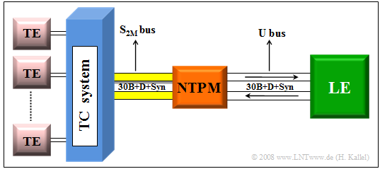
Larger companies usually work with a primary rate interface $\rm (PRI)$, to which the telecommunications or data processing equipment is connected by a four-wire line. The primary rate interface according to the adjacent diagram offers:
- $30$ full-duplex basic channels with $\text{64 kbit/s}$ each,
- one signaling channel $($"data channel"$)$ with $\text{64 kbit/s}$,
- one synchronization channel (also with $\text{64 kbit/s})$, and accordingly
- a gross data rate of $32 · 64 \hspace{0.15cm}\underline{ = 2048 \ \rm kbit/s}$.
It follows some general information about the primary rate interface:
- The $30$ user channels are implemented with the "PCM-30" multiplex system. In contrast to the basic rate interface, only a point-to-point connection is possible here. This means that a second system cannot be connected to the same line as with a bus.
- The telecommunications system is connected to the local exchange via the network termination equipment $($"Network Termination for Primary Rate Multiplex Access" ⇒ "$\rm NTPM$"$)$. This connection is four-wire ⇒ both transmission directions are separated. Thus, no direction separation procedures $($fork circuit, echo cancellation, etc.$)$ are required in the NTPM and in the local exchange.
- The "reference point" $\rm U$ between the network termination and the local exchange is designated $\rm U_{K2}$ in the case of a primary multiplex connection if a copper cable $\rm (K)$ is used; the $\rm (2)$ stands for the transmission rate of $\text{2 Mbit/s}$. In the case of a fiber optic connection, this point is called $\rm U_{G2}$.
- Accordingly, the connection between the network termination and the TC system is generally referred to as the "$\rm S_{2M}$" interface. Technically, however, there is not much difference between the "$\rm U_{K2}$" and the "$\rm S_{2M}$" interfaces.
Frame structure of S2M and UK2 interface
The $\rm S_{2M}$ interface represents the connection between the telecommunications system and the network termination $\rm (NTPM)$, which is implemented with two copper pairs. Since only point-to-point operation is possible here, the $\rm S_{2M}$ interface is not designed as a bus like the $\rm S_{0}$ interface in the basic connection, and therefore no collision detection method is required here.
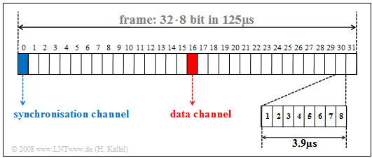
The graphic shows the frame structure of the $\rm S_{2M}$ interface. It can be seen:
- In time division multiplex, a TDMA frame is transmitted every $125\ \rm µs$. However, each of the $32$ channels occupies the TDMA frame only for the duration of $125\ \rm µs/32 = 3.906 \ \rm µs$.
- Eight bits are transmitted per channel and TDMA frame; the bit duration is
- $$T_\text{B} = 3.906 \ \rm µs/8 = 0.488 \ \rm µs.$$
- The reciprocal of this is the gross data rate
- $$R_\text{B} \hspace{0.15cm}\underline{= 2.048 \ \rm Mbit/s}.$$
- The channels 1 to 15 and 17 to 31 represent the bearer ($\rm B)$ channels, all of which are operated independently of each other at $64 \ \rm kbit/s$.
- The data channel 16 $($marked red in the graph$)$ provides control of these user channels and the entire telephone system.
- The synchronization channel 0 $($marked in blue$)$ is used for frame detection in the case of odd frames $($with number $1, 3, 5,$ ...$)$, while the even frames ($2, 4, 6,$ ...$)$ are used for maintenance purposes and for error handling. Both are done with the help of the $\rm CRC4$ method, which is described in more detail in the next section.
The $\rm U_{K2}$ interface has exactly the same properties as the $\rm S_{2M}$ interface and thus also has the same frame structure.
Frame synchronization
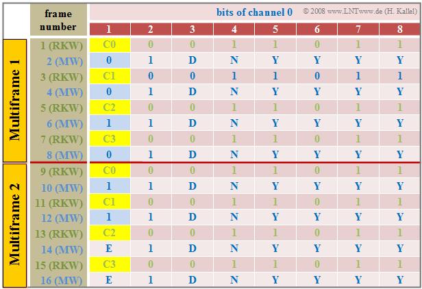
Synchronization is implemented in the channel "0" of a frame in the primary rate interface. The table shows the respective frame assignment of this synchronization channel for one cycle of the CRC4 method. The "Cyclic Redundancy Check" $\rm (CRC4)$ is used for this purpose, which can be illustrated briefly as follows:
- Channel "0" of each odd time frame $($number 1, 3, ... , 15$)$ includes the "frame password" $($German: "Rahmenkennwort" ⇒ "RKW"$)$, while each even frame $($number 2, 4, ... , 16$)$ of this channel contains the "message word".
- Based on the frame password with the fixed bit pattern "$\rm X001\hspace{0.08cm} 1011$", the synchronization between the transmission and the reception direction is established. The first bit $\rm X ∈ {0, 1}$ is determined by the CRC4 method.
- The message word is "$\rm X1DN\hspace{0.08cm} YYYY$". Error messages are signaled via the $\rm D$ bit and the $\rm N$ bit. The four $\rm Y$ bits are reserved for service functions. The $\rm X$ bit is again obtained by the CRC4 method.
- The CRC4 method requires $16$ $\rm X$ bits ⇒ $16$ consecutive pulse frames, which are divided into two multiple frames. The length of a multiple frame is therefore $8 · 256 = 2048$ bits and the time duration is $8 · 0.125 = 1$ millisecond.
- The CRC4 checksum is formed as a sequence of four bits $(\rm C0$, ... , $\rm C3)$ in each multiple frame and provides the first bit $\rm (X)$ for each of four consecutive frame identifiers.
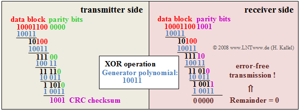
$\text{Example 2:}$ The procedure of the CRC4 method shall be explained by an example, where for the generator polynomial is assumed:
- $$D^4 + D + 1$$
In the binary representation this is: "$10011$". The graph shows the extraction of the CRC4 checksum (left) and its evaluation at the receiver (right). You can see:
- The CRC4 checksum at the transmitter-side results as the remainder of the division of a data block with a total of twelve bits $($eight useful bits, here "$1000\hspace{0.05cm} 1100$", to which "$0000$" is appended$)$ by the generator polynomial "$10011$".
- In polynomial notation, the remainder of the division
- $$(D^{11} + D^7 + D^6 ) : ( D^4 + D + 1)$$
- results in $R(D) = D^3 + 1$ ⇒ binary "$1001$".
- The division is realized by a "modulo-2 addition" $($bitwise XOR operation$)$. In the example, the division yields the remainder "$1001$".
- These bits $\rm C0$, ... , $\rm C3$ of the CRC checksum are transmitted to the receiver in different frames of the synchronization channel $($see frame assignment in the above graphic$)$.
- After the receiver has received these twelve bits $($data block and CRC4 checksum$)$, it also divides this 12-digit binary word by the generator polynomial. In the example, this division "$1000\hspace{0.05cm} 1100\hspace{0.05cm} 1001$" divided by "$10011$" gives the remainder zero. This result indicates that no transmission errors have occurred.
- If the division remainder is not zero, the result indicates a transmission error. In this case, the data must be requested again from the transmitter.
Telecommunications aspects
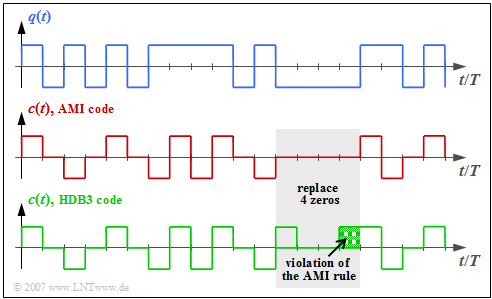
With the ISDN primary rate interface, the so-called HDB3 line code $($High Density Bipolar 3ary$)$ is used on the $\rm S_{2M}$ interface and also on the $\rm U_{K2}$ interface. Compared to the modified AMI code on the $\rm S_{0}$ interface of the base connection
- the occurrence of long zero sequences is avoided, and thus
- providing the receiver a more reliable clock recovery and synchronization.
HDB3 line coding works as follows:
- As in the AMI code, each binary "0" is assigned the signal level $\rm 0\hspace{0.09cm} V$, while the binary "1" is alternately represented by the values $+s_0$ and $–s_0$.
- If four consecutive "0" bits occur in the AMI encoded signal, they are replaced by a sequence of four other bits that violate the AMI coding rule.
- If, as in the above figure, the number of "ones" is even or zero and the last pulse before these four bits is negative, "0 0 0 0" is replaced by the sequence "+ 0 0 +". On the other hand, if the last pulse before these four bits were positive, "0 0 0 0" would be replaced by "– 0 0 –".
- If there were an odd number of "ones" before this "0 0 0 0" block, on the other hand, "0 0 0 +" $($if last pulse positive$)$ or "0 0 0 –" $($if last pulse negative$)$ would be selected as replacements. The DC freedom is maintained by these measures.
- In all four cases, the decoder can detect the violation of the AMI rule and replace this block again with "0 0 0 0".
Exercises for the chapter
Exercise 1.6: Cyclic Redundancy Check
