Difference between revisions of "Examples of Communication Systems/Further Developments of ISDN"
| (23 intermediate revisions by 6 users not shown) | |||
| Line 7: | Line 7: | ||
| − | == | + | ==Broadband ISDN == |
| + | <br> | ||
| + | Broadband ISDN – usually abbreviated as $\text{B–ISDN}$ – was a advancement of ISDN. The aim of this further development from 1996 was to enable new communications services with higher bandwidths in addition to the services and applications of narrowband ISDN. B-ISDN supports, for example, audiovisual services and multimedia applications such as video transmission, videophone and videoconferencing with transmission rates of up to a maximum of $\text{155 Mbps}$. | ||
| − | + | To achieve such a large transmission rate, B-ISDN uses the following new technologies: | |
| − | + | *Instead of copper cables, optical fibers are used, which enable greater bandwidths and ranges due to their low attenuation. The advantages of '''fiber optic technology''' are summarized in the next section. | |
| − | * | ||
| − | |||
| − | |||
| − | + | *'''ATM technology''' $($'''A'''synchronous '''T'''ransfer '''M'''ode$)$ is used to transmit and switch the information. The last section explains this technology for broadband ISDN. | |
| − | + | *The local and long-distance exchanges are specially designed for these large bandwidths. | |
| + | |||
| + | [[File:EN_Bei_T_1_4_S1_neu.png|right|frame|Narrowband ISDN (below) and broadband ISDN (above) in comparison]] | ||
| + | |||
| + | |||
| + | The graphic shows | ||
| + | *below an ISDN network with two bearer channels ("narrowband ISDN") via a copper twisted pair ("Co–TP"), | ||
| + | |||
| + | *compared with broadband ISDN via fiber optic cable $\rm (FOC)$ at the top. | ||
| + | |||
| + | *Signaling takes place via another copper twisted pair (in the center). | ||
| + | |||
| + | |||
| + | Broadband ISDN failed to achieve great commercial success because this technology was very expensive and sufficient bandwidths could also be achieved with [[Examples_of_Communication_Systems/General_Description_of_DSL#.23_OVERVIEW_OF_THE_SECOND_MAIN_CHAPTER_.23|$\rm DSL$]] ("Digital Subscriber Line"). | ||
| + | *The high costs are related to the fact that the optical fiber must be laid all the way to the subscriber. | ||
| + | |||
| + | *However, larger (and therefore less flexible) companies and public authorities use B-ISDN for a longer time, with data rates of up to $\text{622 Mbit/s}$ being achieved after further modifications. | ||
| − | == | + | ==Fiber optic technology == |
| + | <br> | ||
| + | [[File:EN_Bei_T_1_4_S2b_neu.png|right|frame|E/O and O/E signal conversion]] | ||
| + | The transmission media used for broadband ISDN were '''fiber optic cables''' $\rm (FOC)$, often also referred to in simplified terms as "optical fibers". | ||
| + | |||
| + | *In the exchanges, electrical-to-optical conversion $\rm (E/O)$ must be performed at the transmitting end by a "laser diode" $\rm (LD)$ or a "light–emitting diode" $\rm (LED)$. | ||
| + | |||
| + | *At the receiver, an optical-electrical reconversion $\rm (O/E)$ by a "photo diode" $\rm (PD)$ is then necessary. In the sketch, "APD" stands for "avalanche photo diode". | ||
| + | <br clear=all> | ||
| + | Since the first attempts in the 1970s, optical transmission technology has made enormous progress and offers many advantages over electrical transmission: | ||
| + | # In a fiber optic cable, signal propagation occurs through a guided electromagnetic field and there are no currents or voltages as in copper cables. A fiber optic cable is therefore "insensitive to electromagnetic noise" and is also much lighter than a copper cable.<br> | ||
| + | # The signal attenuation of an optical fiber is significantly lower than that of a copper cable. At the attenuation minimum at the wavelength $λ = 1.55 \ µ{\rm m}$, a value of $\text{0.2 dB/km}$ is reached.<br> | ||
| + | # For comparison: For a copper cable with a diameter of 0.4 mm, the attenuation value for a DC signal is about $\text{5 dB/km}$ and for a megahertz about $\text{20 dB/km}$ – see section [[Examples_of_Communication_Systems/General_Description_of_ISDN#Attenuation_behavior_of_copper_cables|"Attenuation behavior of copper cables"]].<br> | ||
| + | # Today (2018), optical fibers can achieve transmission rates of $\text{100 Gbit/s}$ and – with intermediate optical amplifiers – distances of several $\text{1000 km}$ and more. Intermediate regenerators are now only used in exchanges, as the routing of data is still largely electronic.<br> | ||
| + | # Current optical transmission systems transport data rates of $\text{100 Gbit/s}$ over a distance of several $\text{1000 km}$ at a single wavelength. There are already (2018) systems commercially available at $\text{400 Gbit/s}$, but using multiple wavelengths.<br> | ||
| + | # "Optical '''W'''avelength '''D'''ivision '''M'''ultiplex" $\rm (WDM)$ allows a large number of channels to be transmitted in parallel. In 2017, a total data rate of $\text{70.4 Tbits/s}$ was thus achieved via one transatlantic submarine cable $\rm (1 \ Tbit = 10^{12} \ bits)$.<br> | ||
| + | # Nowadays, fiber is mainly used between exchanges, while existing copper lines continue to be used between subscribers and exchanges for cost reasons. In the longer term, however, there will certainly be [https://en.wikipedia.org/wiki/Fiber-optic_communication $\text{Fiber–to–the–Home}$] $\rm (FttH)$. | ||
| + | |||
| + | |||
| + | |||
| + | |||
| + | |||
| + | |||
| + | ==U<sub>G2</sub> interface== | ||
| + | <br> | ||
| + | In a fiber optic connection, the reference point between the network termination and the local exchange is referred to as $\rm U_{G2}$. This interface consists of two optical fibers for the two transmission directions. | ||
| − | + | [[File:EN_Bei_T_1_4_S3.png|right|frame|Conversion from HDB3 to 1T2B code <br>$11$: positive; $00$: negative; $01$: zero volt; $10$: undefined''']] | |
| − | + | *Since it is not possible to transmit the ternary '''HDB3 code''' with the value set $\{–1, \ 0, +1\}$ of the $\rm S_{2M}$ interface in optical form without a complex optical modulator, this must be converted back into a binary code with the elements $0$ and $1$ for the $\rm U_{G2}$ interface. | |
| − | * | ||
| − | |||
| − | |||
| − | |||
| − | |||
| − | |||
| − | |||
| − | + | *This conversion is done redundantly with the '''1T2B code'''. This means: Each ternary symbol is represented by two binary symbols according to the given table. The code redundancy here is equal to $1 – \log_2 \hspace{0.05cm} (3)/2 ≈ 20.7\%$. | |
| − | |||
| − | |||
| − | + | This results in the following properties: | |
| − | + | # The conversion doubles the step rate to $\text{4096 kbit/s}$, which is in principle a disadvantage, but is more than compensated by the advantages of optical transmission. | |
| − | + | # A real disadvantage is the additional effort required by the receiver to convert the optical signal into an electrical signal. | |
| − | == | + | ==ATM technology == |
| + | <br> | ||
| + | Broadband ISDN is based on the so-called '''ATM technology''' $($'''A'''synchronous '''T'''ransfer '''M'''ode$)$. Compared with $\text{PCM 30}$, ATM offers the following advantages for broadband services and applications: | ||
| + | [[File:EN_Bei_T_1_4_S2.png|right|frame|ATM cell structure]] | ||
| + | *Flexible access to the data, and | ||
| + | |||
| + | *good adaptation to high bit rates. | ||
| + | |||
| + | |||
| + | Here follows only a brief description of the [https://en.wikipedia.org/wiki/Asynchronous_Transfer_Mode $\text{ATM method}$] and how it works: | ||
| + | |||
| + | *ATM is a special connection-oriented packet switching. | ||
| + | |||
| + | *The packets here are called "ATM cells". | ||
| + | |||
| + | *Therefore it is a packet-oriented transmission of cells. | ||
| + | |||
| − | + | Each ATM cell is composed of $53$ bytes and consists of | |
| − | * | + | *the cell header $(5$ bytes$)$, and |
| − | |||
| − | + | *an information field $(48$ bytes$)$, which is used for the transmission of user information or signaling data. | |
| − | |||
| − | |||
| − | |||
| − | |||
| − | |||
| − | |||
| − | |||
| − | + | The cell header contains: | |
| − | + | # the "Generic Flow Control" $\rm (GFC)$ ⇒ $4$ bits to control the cell flow, | |
| + | # the "Virtual Path Identifier" $\rm (VPI)$ ⇒ $8$ bits for virtual path identification, | ||
| + | # the "Virtual Channel Identifier" $\rm (VCI)$ ⇒ $16$ bits for virtual channel identification, | ||
| + | # the "Payload Type" $\rm (PT)$ ⇒ $3$ bits to describe the cell type, | ||
| + | # the "Cell Loss Priority" $\rm (CLP)$ ⇒ $1$ bit to detect a cell loss, | ||
| + | # the "Header Error Control" $\rm (HEC)$ ⇒ $8$ bits to avoid bit errors in the cell header. | ||
| + | |||
| + | |||
| + | In ATM technology, cells arriving asynchronously from the terminals are transmitted using "Time Division Multiplexing". | ||
| + | *If no cells arrive, empty cells are generated so that there is always a continuous stream of cells on the line. | ||
| + | |||
| + | *ATM is asynchronous in the sense that cells with user information do not have to occur periodically. | ||
| + | |||
| + | *Further information on ATM can be found in the second main chapter [[Examples_of_Communication_Systems/xDSL_Systems|$\rm DSL$]] ("Digital Subscriber Line") in this book, which also uses ATM technology. | ||
| − | == | + | ==Exercise for the chapter == |
| + | <br> | ||
| + | [[Aufgaben:Exercise_1.7:_Coding_for_B-ISDN|Exercise 1.7: Coding for B-ISDN]] | ||
Latest revision as of 12:13, 10 November 2022
Contents
Broadband ISDN
Broadband ISDN – usually abbreviated as $\text{B–ISDN}$ – was a advancement of ISDN. The aim of this further development from 1996 was to enable new communications services with higher bandwidths in addition to the services and applications of narrowband ISDN. B-ISDN supports, for example, audiovisual services and multimedia applications such as video transmission, videophone and videoconferencing with transmission rates of up to a maximum of $\text{155 Mbps}$.
To achieve such a large transmission rate, B-ISDN uses the following new technologies:
- Instead of copper cables, optical fibers are used, which enable greater bandwidths and ranges due to their low attenuation. The advantages of fiber optic technology are summarized in the next section.
- ATM technology $($Asynchronous Transfer Mode$)$ is used to transmit and switch the information. The last section explains this technology for broadband ISDN.
- The local and long-distance exchanges are specially designed for these large bandwidths.
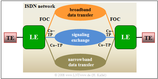
The graphic shows
- below an ISDN network with two bearer channels ("narrowband ISDN") via a copper twisted pair ("Co–TP"),
- compared with broadband ISDN via fiber optic cable $\rm (FOC)$ at the top.
- Signaling takes place via another copper twisted pair (in the center).
Broadband ISDN failed to achieve great commercial success because this technology was very expensive and sufficient bandwidths could also be achieved with $\rm DSL$ ("Digital Subscriber Line").
- The high costs are related to the fact that the optical fiber must be laid all the way to the subscriber.
- However, larger (and therefore less flexible) companies and public authorities use B-ISDN for a longer time, with data rates of up to $\text{622 Mbit/s}$ being achieved after further modifications.
Fiber optic technology
The transmission media used for broadband ISDN were fiber optic cables $\rm (FOC)$, often also referred to in simplified terms as "optical fibers".
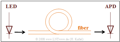
- In the exchanges, electrical-to-optical conversion $\rm (E/O)$ must be performed at the transmitting end by a "laser diode" $\rm (LD)$ or a "light–emitting diode" $\rm (LED)$.
- At the receiver, an optical-electrical reconversion $\rm (O/E)$ by a "photo diode" $\rm (PD)$ is then necessary. In the sketch, "APD" stands for "avalanche photo diode".
Since the first attempts in the 1970s, optical transmission technology has made enormous progress and offers many advantages over electrical transmission:
- In a fiber optic cable, signal propagation occurs through a guided electromagnetic field and there are no currents or voltages as in copper cables. A fiber optic cable is therefore "insensitive to electromagnetic noise" and is also much lighter than a copper cable.
- The signal attenuation of an optical fiber is significantly lower than that of a copper cable. At the attenuation minimum at the wavelength $λ = 1.55 \ µ{\rm m}$, a value of $\text{0.2 dB/km}$ is reached.
- For comparison: For a copper cable with a diameter of 0.4 mm, the attenuation value for a DC signal is about $\text{5 dB/km}$ and for a megahertz about $\text{20 dB/km}$ – see section "Attenuation behavior of copper cables".
- Today (2018), optical fibers can achieve transmission rates of $\text{100 Gbit/s}$ and – with intermediate optical amplifiers – distances of several $\text{1000 km}$ and more. Intermediate regenerators are now only used in exchanges, as the routing of data is still largely electronic.
- Current optical transmission systems transport data rates of $\text{100 Gbit/s}$ over a distance of several $\text{1000 km}$ at a single wavelength. There are already (2018) systems commercially available at $\text{400 Gbit/s}$, but using multiple wavelengths.
- "Optical Wavelength Division Multiplex" $\rm (WDM)$ allows a large number of channels to be transmitted in parallel. In 2017, a total data rate of $\text{70.4 Tbits/s}$ was thus achieved via one transatlantic submarine cable $\rm (1 \ Tbit = 10^{12} \ bits)$.
- Nowadays, fiber is mainly used between exchanges, while existing copper lines continue to be used between subscribers and exchanges for cost reasons. In the longer term, however, there will certainly be $\text{Fiber–to–the–Home}$ $\rm (FttH)$.
UG2 interface
In a fiber optic connection, the reference point between the network termination and the local exchange is referred to as $\rm U_{G2}$. This interface consists of two optical fibers for the two transmission directions.
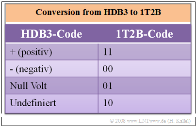
- Since it is not possible to transmit the ternary HDB3 code with the value set $\{–1, \ 0, +1\}$ of the $\rm S_{2M}$ interface in optical form without a complex optical modulator, this must be converted back into a binary code with the elements $0$ and $1$ for the $\rm U_{G2}$ interface.
- This conversion is done redundantly with the 1T2B code. This means: Each ternary symbol is represented by two binary symbols according to the given table. The code redundancy here is equal to $1 – \log_2 \hspace{0.05cm} (3)/2 ≈ 20.7\%$.
This results in the following properties:
- The conversion doubles the step rate to $\text{4096 kbit/s}$, which is in principle a disadvantage, but is more than compensated by the advantages of optical transmission.
- A real disadvantage is the additional effort required by the receiver to convert the optical signal into an electrical signal.
ATM technology
Broadband ISDN is based on the so-called ATM technology $($Asynchronous Transfer Mode$)$. Compared with $\text{PCM 30}$, ATM offers the following advantages for broadband services and applications:
- Flexible access to the data, and
- good adaptation to high bit rates.
Here follows only a brief description of the $\text{ATM method}$ and how it works:
- ATM is a special connection-oriented packet switching.
- The packets here are called "ATM cells".
- Therefore it is a packet-oriented transmission of cells.
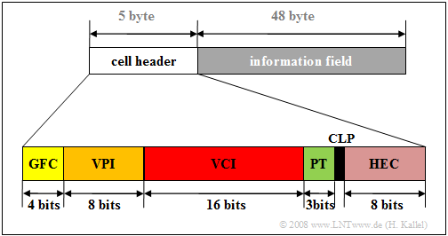
Each ATM cell is composed of $53$ bytes and consists of
- the cell header $(5$ bytes$)$, and
- an information field $(48$ bytes$)$, which is used for the transmission of user information or signaling data.
The cell header contains:
- the "Generic Flow Control" $\rm (GFC)$ ⇒ $4$ bits to control the cell flow,
- the "Virtual Path Identifier" $\rm (VPI)$ ⇒ $8$ bits for virtual path identification,
- the "Virtual Channel Identifier" $\rm (VCI)$ ⇒ $16$ bits for virtual channel identification,
- the "Payload Type" $\rm (PT)$ ⇒ $3$ bits to describe the cell type,
- the "Cell Loss Priority" $\rm (CLP)$ ⇒ $1$ bit to detect a cell loss,
- the "Header Error Control" $\rm (HEC)$ ⇒ $8$ bits to avoid bit errors in the cell header.
In ATM technology, cells arriving asynchronously from the terminals are transmitted using "Time Division Multiplexing".
- If no cells arrive, empty cells are generated so that there is always a continuous stream of cells on the line.
- ATM is asynchronous in the sense that cells with user information do not have to occur periodically.
- Further information on ATM can be found in the second main chapter $\rm DSL$ ("Digital Subscriber Line") in this book, which also uses ATM technology.
Exercise for the chapter
Exercise 1.7: Coding for B-ISDN


