Difference between revisions of "Signal Representation/Harmonic Oscillation"
| Line 21: | Line 21: | ||
{{BlaueBox|TEXT= | {{BlaueBox|TEXT= | ||
$\text{Definition:}$ | $\text{Definition:}$ | ||
| − | + | Any '''harmonic oscillation''' can be represented in most general form as follows: | |
:$$x(t)= C \cdot \cos(2\pi f_0 t - \varphi).$$ | :$$x(t)= C \cdot \cos(2\pi f_0 t - \varphi).$$ | ||
| − | + | The following signal parameters are used: | |
| − | * | + | *the '''amplitude''' $C$ – simultaneously the maximum value of the signal, |
| − | * | + | *the '''signal frequency''' $f_{0}$ ⇒ the reciprocal of the period duration $T_{0}$, and |
| − | * | + | *the '''zero phase angle''' (or briefly the ''phase'') $\varphi$ of the oscillation.}} |
| − | + | The german learning video [[Harmonische_Schwingungen_(Lernvideo)|Harmonic Oscillations]] illustrates the properties of harmonic oscillations using scales. | |
{{BlaueBox|TEXT= | {{BlaueBox|TEXT= | ||
| − | $\text{ | + | $\text{Comments on nomenclature:}$ |
| − | *In | + | *In this tutorial - as usual in other literature - when describing harmonic oscillations, Fourier series and Fourier integral, the phase is entered into the equations with a negative sign, whereas in connection with all modulation methods the phase is always entered with a plus sign. |
| − | * | + | *To distinguish between the two variants we use in $\rm LNTwww$ $\varphi$ and $\phi$. Both symbols denote the small Greek "phi". The spelling $\varphi$ is mainly used in the German and $\phi$ in the anglo–american language area. |
| − | * | + | *The indications $\varphi = 90^{\circ}$ and $\phi = -90^{\circ}$ are thus equivalent and both stand for the sine function: |
:$$\cos(2 \pi f_0 t - 90^{\circ}) = \cos(2 \pi f_0 t - \varphi) = \cos(2 \pi f_0 t + \phi) = \sin(2 \pi f_0 t ).$$}} | :$$\cos(2 \pi f_0 t - 90^{\circ}) = \cos(2 \pi f_0 t - \varphi) = \cos(2 \pi f_0 t + \phi) = \sin(2 \pi f_0 t ).$$}} | ||
| − | == | + | ==Time Signal Representation== |
<br> | <br> | ||
| − | [[File:P_ID129__Sig_T_2_3_S2a.png|right|frame| | + | [[File:P_ID129__Sig_T_2_3_S2a.png|right|frame|Signal Parameters of a Harmonic Oscillation]] |
| − | + | The amplitude $C$ can be read directly from the adjacent graphic. The signal frequency $f_0$ is equal to the reciprocal of the period duration $T_0$. If the above equation is written in the form | |
:$$x(t) = C \cdot \cos(2\pi f_0 t - \varphi) = C \cdot \cos \big(2\pi f_0 (t - \tau) \big), $$ | :$$x(t) = C \cdot \cos(2\pi f_0 t - \varphi) = C \cdot \cos \big(2\pi f_0 (t - \tau) \big), $$ | ||
| − | + | it becomes clear that the zero phase angle $\varphi$ and the displacement $\tau$ relative to a cosine signal are related as follows | |
:$$\varphi = \frac{\tau}{T_0} \cdot 2{\pi}. $$ | :$$\varphi = \frac{\tau}{T_0} \cdot 2{\pi}. $$ | ||
| − | * | + | *For a ''cosine signal'' the parameters $\tau$ and $\varphi$ are zero. |
| − | * | + | *In contrast, a ''sinusoidal signal'' is shifted by $\tau = T_0/4$ and accordingly applies to the zero phase angle $\varphi = \pi/2$ (in radians) or $90^{\circ}$. |
| − | + | So it can be stated, that - as assumed for the above sketch - at a positive value of $\tau$ resp. $\varphi$ the $($referring $t = 0)$ nearest signal maximum comes later than at the cosine signal and at negative values earlier. If a cosine signal is present at the system input and the output signal is delayed by a value $\tau$ then the system is called $\tau$ also called the '''runtime''' . | |
| − | + | Since a harmonic oscillation is clearly defined by only three signal parameters, the entire time course from $-\infty$ to $+\infty$ can be calculated from only three signal values $x_1=x(t_1)$, $x_2=x(t_2)$, $x_3=x(t_3)$ can be described analytically if the times $t_1$, $t_2$ and $t_3$ have been determined appropriately. | |
| − | [[File:P_ID2717__Sig_T_2_3_S2b_neu.png|right|frame| | + | [[File:P_ID2717__Sig_T_2_3_S2b_neu.png|right|frame|Harmonic Oscillation, defined by <br>Three Samples]] |
{{GraueBox|TEXT= | {{GraueBox|TEXT= | ||
| − | $\text{ | + | $\text{Example 1:}$ |
| − | + | From the three sample values, | |
:$$x_1 = x(t_1 = 3.808 \;{\rm ms}) = +1.609,$$ | :$$x_1 = x(t_1 = 3.808 \;{\rm ms}) = +1.609,$$ | ||
:$$x_2 = x(t_2 = 16.696 \;{\rm ms})=\hspace{0.05 cm} -0.469,$$ | :$$x_2 = x(t_2 = 16.696 \;{\rm ms})=\hspace{0.05 cm} -0.469,$$ | ||
:$$x_3 = x(t_3 = 33.84 \;{\rm ms}) = +1.227$$ | :$$x_3 = x(t_3 = 33.84 \;{\rm ms}) = +1.227$$ | ||
| − | + | you get the following system of equations: | |
:$$C \cdot \cos(2\pi \hspace{0.05 cm} f_0 \hspace{0.05 cm} t_1 - \varphi) = +1.609\hspace{0.05 cm},$$ | :$$C \cdot \cos(2\pi \hspace{0.05 cm} f_0 \hspace{0.05 cm} t_1 - \varphi) = +1.609\hspace{0.05 cm},$$ | ||
| Line 75: | Line 75: | ||
:$$C \cdot \cos(2\pi \hspace{0.05 cm} f_0 \hspace{0.05 cm} t_3 - \varphi) = +1.227\hspace{0.05 cm}.$$ | :$$C \cdot \cos(2\pi \hspace{0.05 cm} f_0 \hspace{0.05 cm} t_3 - \varphi) = +1.227\hspace{0.05 cm}.$$ | ||
| − | + | After solving this nonlinear system of equations the following signal parameters are obtained: | |
| − | * | + | *Signal amplitude $C = 2$, |
| − | * | + | *Period duration $T_0 = 8 \;{\rm ms}$ ⇒ Signal frequency $f_0 = 125 \;{\rm Hz}$, |
| − | * | + | *displacement with respect to a cosine $\tau = 3 \;{\rm ms}$ ⇒ zero phase angle $\varphi = 3\pi /4 = 135^\circ$. |
| − | '' | + | ''Note'': If you set all sampling times $t_1$, $t_2$, $t_3$ in maxima, minima and/or zeros, there is no unique solution for the nonlinear system of equations.}} |
| − | == | + | ==Representation with Cosine and Sine Components== |
<br> | <br> | ||
Eine weitere Darstellungsform der harmonischen Schwingung lautet wie folgt: | Eine weitere Darstellungsform der harmonischen Schwingung lautet wie folgt: | ||
| Line 90: | Line 90: | ||
:$$x(t)=A\cdot\cos(2\pi f_0 t)+ B\cdot\sin(2\pi f_0 t).$$ | :$$x(t)=A\cdot\cos(2\pi f_0 t)+ B\cdot\sin(2\pi f_0 t).$$ | ||
| − | * | + | *The terms $A$ and $B$ for the amplitudes of the cosine and sine components are chosen to match the nomenclature of the following chapter[Signal_Representation/Fourier_Series| Fourier Series]] . |
| − | * | + | *By applying trigonometric transformations we obtain from the illustration on the last page |
:$$x(t)=C\cdot \cos(2\pi f_0 t-\varphi)=C\cdot\cos(\varphi)\cdot\cos(2\pi f_0 t)+C\cdot\sin(\varphi)\cdot\sin(2\pi f_0 t).$$ | :$$x(t)=C\cdot \cos(2\pi f_0 t-\varphi)=C\cdot\cos(\varphi)\cdot\cos(2\pi f_0 t)+C\cdot\sin(\varphi)\cdot\sin(2\pi f_0 t).$$ | ||
| − | * | + | *From this follows directly by equating the coefficients: |
:$$A=C\cdot\cos(\varphi),\hspace{0.5cm}B=C\cdot\sin(\varphi).$$ | :$$A=C\cdot\cos(\varphi),\hspace{0.5cm}B=C\cdot\sin(\varphi).$$ | ||
| − | * | + | *The magnitude and the zero phase angle of the harmonic oscillation can be calculated from the parameters $A$ and $B$ also according to simple trigonometric considerations |
:$$C=\sqrt{A^2+B^2}, \hspace{0.5 cm}\varphi = \arctan\left({-B}/{A}\right).$$ | :$$C=\sqrt{A^2+B^2}, \hspace{0.5 cm}\varphi = \arctan\left({-B}/{A}\right).$$ | ||
{{BlaueBox|TEXT= | {{BlaueBox|TEXT= | ||
| − | $\text{ | + | $\text{Please consider:}$ |
Das Minuszeichen bei der Berechnung des Nullphasenwinkels $\varphi$ hängt damit zusammen, dass $\varphi$ in das Argument der Cosinusfunktion mit negativem Vorzeichen eingeht. | Das Minuszeichen bei der Berechnung des Nullphasenwinkels $\varphi$ hängt damit zusammen, dass $\varphi$ in das Argument der Cosinusfunktion mit negativem Vorzeichen eingeht. | ||
Revision as of 20:40, 11 October 2020
Contents
Definition and Properties
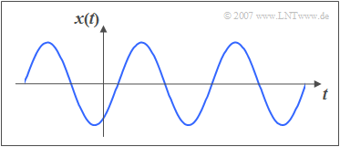
Harmonic oscillations are of particular importance for communications engineering as well as in many natural sciences. The following diagram shows an exemplary signal waveform.
Its importance is also related to the fact that the harmonic oscillation represents the solution of a Differential equation which is found in many disciplines and reads as follows
- $$ x(t) + k \cdot\ddot{x} (t) = 0.$$
Here the two dots mark the second derivative of the function $x(t)$ after time.
$\text{Definition:}$ Any harmonic oscillation can be represented in most general form as follows:
- $$x(t)= C \cdot \cos(2\pi f_0 t - \varphi).$$
The following signal parameters are used:
- the amplitude $C$ – simultaneously the maximum value of the signal,
- the signal frequency $f_{0}$ ⇒ the reciprocal of the period duration $T_{0}$, and
- the zero phase angle (or briefly the phase) $\varphi$ of the oscillation.
The german learning video Harmonic Oscillations illustrates the properties of harmonic oscillations using scales.
$\text{Comments on nomenclature:}$
- In this tutorial - as usual in other literature - when describing harmonic oscillations, Fourier series and Fourier integral, the phase is entered into the equations with a negative sign, whereas in connection with all modulation methods the phase is always entered with a plus sign.
- To distinguish between the two variants we use in $\rm LNTwww$ $\varphi$ and $\phi$. Both symbols denote the small Greek "phi". The spelling $\varphi$ is mainly used in the German and $\phi$ in the anglo–american language area.
- The indications $\varphi = 90^{\circ}$ and $\phi = -90^{\circ}$ are thus equivalent and both stand for the sine function:
- $$\cos(2 \pi f_0 t - 90^{\circ}) = \cos(2 \pi f_0 t - \varphi) = \cos(2 \pi f_0 t + \phi) = \sin(2 \pi f_0 t ).$$
Time Signal Representation
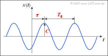
The amplitude $C$ can be read directly from the adjacent graphic. The signal frequency $f_0$ is equal to the reciprocal of the period duration $T_0$. If the above equation is written in the form
- $$x(t) = C \cdot \cos(2\pi f_0 t - \varphi) = C \cdot \cos \big(2\pi f_0 (t - \tau) \big), $$
it becomes clear that the zero phase angle $\varphi$ and the displacement $\tau$ relative to a cosine signal are related as follows
- $$\varphi = \frac{\tau}{T_0} \cdot 2{\pi}. $$
- For a cosine signal the parameters $\tau$ and $\varphi$ are zero.
- In contrast, a sinusoidal signal is shifted by $\tau = T_0/4$ and accordingly applies to the zero phase angle $\varphi = \pi/2$ (in radians) or $90^{\circ}$.
So it can be stated, that - as assumed for the above sketch - at a positive value of $\tau$ resp. $\varphi$ the $($referring $t = 0)$ nearest signal maximum comes later than at the cosine signal and at negative values earlier. If a cosine signal is present at the system input and the output signal is delayed by a value $\tau$ then the system is called $\tau$ also called the runtime .
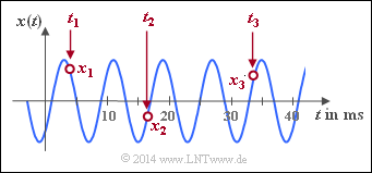
Since a harmonic oscillation is clearly defined by only three signal parameters, the entire time course from $-\infty$ to $+\infty$ can be calculated from only three signal values $x_1=x(t_1)$, $x_2=x(t_2)$, $x_3=x(t_3)$ can be described analytically if the times $t_1$, $t_2$ and $t_3$ have been determined appropriately.
$\text{Example 1:}$ From the three sample values,
- $$x_1 = x(t_1 = 3.808 \;{\rm ms}) = +1.609,$$
- $$x_2 = x(t_2 = 16.696 \;{\rm ms})=\hspace{0.05 cm} -0.469,$$
- $$x_3 = x(t_3 = 33.84 \;{\rm ms}) = +1.227$$
you get the following system of equations:
- $$C \cdot \cos(2\pi \hspace{0.05 cm} f_0 \hspace{0.05 cm} t_1 - \varphi) = +1.609\hspace{0.05 cm},$$
- $$C \cdot \cos(2\pi \hspace{0.05 cm} f_0 \hspace{0.05 cm} t_2 - \varphi) = \hspace{0.05 cm} -0.469\hspace{0.05 cm},$$
- $$C \cdot \cos(2\pi \hspace{0.05 cm} f_0 \hspace{0.05 cm} t_3 - \varphi) = +1.227\hspace{0.05 cm}.$$
After solving this nonlinear system of equations the following signal parameters are obtained:
- Signal amplitude $C = 2$,
- Period duration $T_0 = 8 \;{\rm ms}$ ⇒ Signal frequency $f_0 = 125 \;{\rm Hz}$,
- displacement with respect to a cosine $\tau = 3 \;{\rm ms}$ ⇒ zero phase angle $\varphi = 3\pi /4 = 135^\circ$.
Note: If you set all sampling times $t_1$, $t_2$, $t_3$ in maxima, minima and/or zeros, there is no unique solution for the nonlinear system of equations.
Representation with Cosine and Sine Components
Eine weitere Darstellungsform der harmonischen Schwingung lautet wie folgt:
- $$x(t)=A\cdot\cos(2\pi f_0 t)+ B\cdot\sin(2\pi f_0 t).$$
- The terms $A$ and $B$ for the amplitudes of the cosine and sine components are chosen to match the nomenclature of the following chapter[Signal_Representation/Fourier_Series| Fourier Series]] .
- By applying trigonometric transformations we obtain from the illustration on the last page
- $$x(t)=C\cdot \cos(2\pi f_0 t-\varphi)=C\cdot\cos(\varphi)\cdot\cos(2\pi f_0 t)+C\cdot\sin(\varphi)\cdot\sin(2\pi f_0 t).$$
- From this follows directly by equating the coefficients:
- $$A=C\cdot\cos(\varphi),\hspace{0.5cm}B=C\cdot\sin(\varphi).$$
- The magnitude and the zero phase angle of the harmonic oscillation can be calculated from the parameters $A$ and $B$ also according to simple trigonometric considerations
- $$C=\sqrt{A^2+B^2}, \hspace{0.5 cm}\varphi = \arctan\left({-B}/{A}\right).$$
$\text{Please consider:}$ Das Minuszeichen bei der Berechnung des Nullphasenwinkels $\varphi$ hängt damit zusammen, dass $\varphi$ in das Argument der Cosinusfunktion mit negativem Vorzeichen eingeht.
Würde man statt „$\cos(2\pi f_0 t - \varphi)$” die Schreibweise „$\cos(2\pi f_0 t + \phi)$” verwenden, so wäre $\phi= \arctan(B/A)$. Hier noch folgender Hinweis:
- Bei Fourierreihe und Fourierintegral ist in der Literatur die $\varphi$–Darstellung üblich.
- Zur Beschreibung der Modulationsverfahren verwendet man dagegen fast immer die $\phi$–Darstellungsform.
$\text{Beispiel 2:}$ Die in der linken Grafik als Zeitverlauf dargestellte Schwingung ist gekennzeichnet durch die Parameter
- $f_0 = 125 \;{\rm Hz}$,
- $\varphi = +135^{\circ}$ ⇒ $\phi = -135^{\circ}$ .
Die Schwingung wird durch jede der beiden Gleichungen vollständig beschrieben:
- $$x(t) \hspace{-0.05cm}=\hspace{-0.05cm} 2\cdot \cos(2\pi f_0 t-135^{\circ})\hspace{0.05cm},$$
- $$x(t) \hspace{-0.05cm}=\hspace{-0.05cm} -\sqrt{2}\cdot \cos(2\pi f_0 t) \hspace{-0.05cm}+\hspace{-0.05cm}\sqrt{2}\cdot \sin(2\pi f_0 t)\hspace{0.05cm}.$$
Die rechte Skizze verdeutlicht die trigonometrische Umformung:
- $$A = 2\cdot \cos(-135^{\circ}) = -\sqrt{2}\hspace{0.05cm},$$
- $$B = 2\cdot \sin(-135^{\circ}) = +\sqrt{2}\hspace{0.05cm}.$$
Spektraldarstellung eines Cosinussignals
Zur Herleitung der Spektralfunktion beschränken wir uns zunächst auf ein Cosinussignal, das mit der komplexen Exponentialfunktion und dem Satz von Euler auch in folgender Weise geschrieben werden kann:
- $$x(t)=A \cdot \cos(2\pi f_0 t)={A}/{2}\cdot \big [{\rm e}^{\rm -j2 \pi \it f_{\rm 0} t} + {\rm e}^{\rm j2\pi \it f_{\rm 0} t} \big ].$$
Bereits aus dieser Zeitbereichsdarstellung ist ersichtlich, dass das Cosinussignal – spektral gesehen – nur eine einzige (physikalische) Frequenz beinhaltet, nämlich die Frequenz $f_0$.
$\text{Beweis:}$ Zur mathematischen Herleitung der Spektralfunktion benutzen wir folgende Beziehungen:
- den auf der Seite Diracfunktion im Frequenzbereich hergeleiteten Funktionalzusammenhang:
- $$x(t)=A \ \circ\!\!-\!\!\!-\!\!\!-\!\!\bullet\, \ X(f)=A \cdot \rm \delta (\it f).$$
- den Verschiebungssatz (für den Frequenzbereich) im Vorgriff auf ein späteres Kapitel:
- $$x(t) \cdot {\rm e}^{\rm j2\pi\it f_{\rm 0} t}\ \circ\!\!-\!\!\!-\!\!\!-\!\!\bullet\, \ X(f-f_0). $$
Daraus ergibt sich die folgende Fourierkorrespondenz:
- $$x(t)=A\cdot \cos(2\pi f_0t)\ \circ\!\!-\!\!\!-\!\!\!-\!\!\bullet\, \ X(f)={A}/{\rm 2}\cdot {\rm \delta} (f+f_{\rm 0})+{A}/{\rm 2}\cdot {\rm \delta}(\ f-f_{\rm 0}).$$
Das bedeutet:
- Die Spektralfunktion $X(f)$ eines Cosinussignals mit der Frequenz $f_0$ setzt sich aus zwei Diracfunktionen bei $\pm f_0$ zusammen.
- Die Impulsgewichte sind jeweils gleich der halben Signalamplitude.
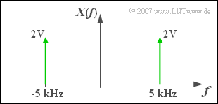
$\text{Beispiel 3:}$ Die Grafik zeigt das Spektrum einer Cosinusschwingung
- mit der Amplitude $A = 4 \;{\rm V}$ und
- der Frequenz $f_0 = 5 \;{\rm kHz}$ ⇒ $T_0 = 200 \;{\rm µ s}$.
Dann gilt folgender Zusammenhang mit obiger Gleichung:
- Die Diracfunktion bei $-f_0$ gehört zum ersten Term $($ableitbar aus der Bedingung $f + f_0 = 0)$.
- Die Diracfunktion bei $+f_0$ gehört zum zweiten Term $($ableitbar aus der Bedingung $f - f_0 = 0)$.
- Die Impulsgewichte sind jeweils $A/2 = 2 \;{\rm V}$.
$\text{Bitte beachten Sie:}$ Die Spektralfunktion einer jeden reellen Zeitfunktion mit Ausnahme des Gleichsignals weist sowohl Anteile bei positiven als auch bei negativen Frequenzen auf.
- Diese Tatsache, die Studienanfängern oft Probleme bereitet, ergibt sich ganz formal aus dem Satz von Euler .
- Durch die Erweiterung des Frequenzwertebereichs von $f \ge 0$ auf die Menge der reellen Zahlen kommt man von der physikalischen zur mathematischen Frequenz.
- Allerdings ist für eine negative Frequenz die vorne angegebene Definition nicht mehr anwendbar: Man kann „–5 kHz” nicht als „minus 5000 Schwingungen pro Sekunde” interpretieren.
Im Verlauf dieses Kurses werden Sie feststellen, dass durch die Verkomplizierung dieses einfachen Sachverhaltes später kompliziertere Sachverhalte sehr elegant und einfach beschrieben werden können.
Allgemeine Spektraldarstellung
Für ein sinusförmiges Signal gilt mit dem Satz von Euler in ähnlicher Weise:
- $$x(t)=B\cdot \sin(2 \pi f_0 t)= \frac{\it B}{2 \rm j} \cdot \big [{\rm e}^{+{\rm j} 2 \pi \it f_{\rm 0} t}-{\rm e}^{-\rm j2 \pi \it f_{\rm 0} t}\big ]=\rm j\cdot {\it B}/{2} \cdot \big [{\rm e}^{-j2 \pi \it f_{\rm 0} t}-{\rm e}^{+\rm j2 \pi \it f_{\rm 0} t} \big ] .$$
Daraus folgt für die Spektralfunktion, die jetzt rein imaginär ist:
- $$x(t)=B\cdot \sin(2\pi f_0 t)\;\ \circ\!\!-\!\!\!-\!\!\!-\!\!\bullet\; \ X(f)={\rm j} \cdot \big [ {B}/{2} \cdot \delta (f+f_0)- {B}/{2} \cdot \delta (f-f_0) \big ].$$
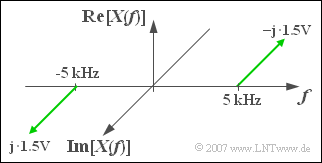
$\text{Beispiel 4:}$ Das Bild zeigt die rein imaginäre Spektralfunktion einer Sinusschwingung $x(t)$ mit
- Amplitude $B = 3 \;{\rm V},$
- Frequenz $f_0 = 5\;{\rm kHz},$
- Phase $\varphi=90^{\circ}$ ⇒ $\phi = -90^{\circ}$.
$\text{Bitte beachten Sie}$:
- Bei der positiven Frequenz $(f = +f_0)$ ist der Imaginärteil negativ.
- Bei der negativen Frequenz $(f = -f_0)$ ergibt sich ein positiver Imaginärteil.
Bei Überlagerung von Cosinus– und Sinusanteil entsprechend der Beziehung
- $$x(t)=A \cdot \cos(2\pi f_0 t) +B \cdot \sin(2 \pi f_0 t)$$
überlagern sich auch die einzelnen Spektralfunktionen und man erhält:
- $$X(f)=\frac{A+{\rm j} \cdot B}{2}\cdot {\rm \delta} (f+f_0)+\frac{A-{\rm j} \cdot B}{2} \cdot \delta (f-f_0).$$
Mit dem Betrag $C$ und der Phase $\varphi$ lautet diese Fourierkorrespondenz:
- $$x(t)=C\cdot \cos(2\pi f_0 t-\varphi)\ \, \circ\!\!-\!\!\!-\!\!\!-\!\!\bullet\,\ X(f)={C}/{2}\cdot {\rm e}^{{\rm j} \varphi} \cdot \delta(f+f_0) + {C}/{2} \cdot {\rm e}^{\rm{-j} \varphi} \cdot \delta (f-f_0).$$
$\text{Man erkennt:}$ Die Spektralfunktion $X(f)$
- ist nicht nur für positive und negative Frequenzen definiert,
- sondern im Allgemeinen auch noch komplexwertig.
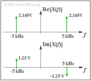
$\text{Beispiel 5:}$ Mit den Parametern $C = 5 \;{\rm V}$, $f_0 = 5\;{\rm kHz}$ und $\varphi=90^{\circ}$ $($im Bogenmaß $\pi/6)$ ergibt sich wegen
- $$2.5 · \cos(30^{\circ}) = 2.165, \hspace{0.3cm} 2.5 · \sin(30^{\circ}) = 1.25$$
der Real- bzw. der Imaginärteil von $X(f)$ gemäß der Grafik:
- $${\rm Re}\big[X(f)\big]=2.165\,{\rm V} \cdot \delta(f+f_0) + 2.165\,{\rm V} \cdot \delta (f-f_0).$$
- $${\rm Im}\big[X(f)\big]=1.25\,{\rm V} \cdot \delta(f+f_0) -1.25\,{\rm V} \cdot \delta (f-f_0).$$
Das Lernvideo
Harmonische Schwingungen verdeutlicht die Eigenschaften harmonischer Schwingungen anhand der so genannten Tonleiter.
Aufgaben zum Kapitel
Aufgabe 2.3: Cosinus- und Sinusanteil
Aufgabe 2.3: Schwingungsparameter
