Difference between revisions of "Aufgaben:Exercise 5.8Z: Matched Filter for Rectangular PSD"
From LNTwww
m (Guenter moved page Exercise 5.8Z: Matched Filter for Rectangular PDS to Exercise 5.8Z: Matched Filter for Rectangular PSD) |
|||
| Line 1: | Line 1: | ||
| − | {{quiz-Header|Buchseite= | + | {{quiz-Header|Buchseite=Theory_of_Stochastic_Signals/Matched_Filter |
}} | }} | ||
| − | [[File:P_ID647__Sto_Z_5_8.png|right|frame| | + | [[File:P_ID647__Sto_Z_5_8.png|right|frame|Useful signal spectrum $G(f)$ and PSD ${\it \Phi}_n (f)$ of the interference]] |
| − | + | The interference power density effective on a system can be assumed to be constant in range: | |
:$$\it{\Phi} _n \left( f \right) = \left\{ \begin{array}{l} N_0 /2 \\ N_1 /2 \\ \end{array} \right.\quad \begin{array}{*{20}c} \rm{f\ddot{u}r} \\ \rm{f\ddot{u}r} \\\end{array}\quad \begin{array}{*{20}c} {\left| f \right| \le f_{\rm N} ,} \\ {\left| f \right| > f_{\rm N} .} \\\end{array}$$ | :$$\it{\Phi} _n \left( f \right) = \left\{ \begin{array}{l} N_0 /2 \\ N_1 /2 \\ \end{array} \right.\quad \begin{array}{*{20}c} \rm{f\ddot{u}r} \\ \rm{f\ddot{u}r} \\\end{array}\quad \begin{array}{*{20}c} {\left| f \right| \le f_{\rm N} ,} \\ {\left| f \right| > f_{\rm N} .} \\\end{array}$$ | ||
| − | * | + | *Here, let the interference power density $N_1$ in the outer region $|f| > f_{\rm N}$ always be much smaller than $N_0$. |
| − | * | + | *For example, use the following values: |
:$$N_0 = 2 \cdot 10^{ - 6} \;{\rm{V}}^{\rm{2}} /{\rm{Hz}},\quad N_1 = 2 \cdot 10^{ - 8} \;{\rm{V}}^{\rm{2}}/ {\rm{Hz}}.$$ | :$$N_0 = 2 \cdot 10^{ - 6} \;{\rm{V}}^{\rm{2}} /{\rm{Hz}},\quad N_1 = 2 \cdot 10^{ - 8} \;{\rm{V}}^{\rm{2}}/ {\rm{Hz}}.$$ | ||
| − | + | Such an interference signal $n(t)$ occurs, for example, when the dominant interference source contains only components below the frequency limit $f_{\rm N}$. Due to the unavoidable thermal noise, also for $|f| > f_{\rm N}$ the interference power density is ${\it \Phi}_n(f) \ne 0$. | |
| − | + | Further, it holds: | |
| − | * | + | *Let the spectrum $G(f)$ of the useful signal also be rectangular according to the above diagram. |
| − | * | + | *Therefore, the corresponding useful pulse $g(t)$ has the following curve with $\Delta f = 2 \cdot f_{\rm G}$: |
:$$g(t) = G_0 \cdot \Delta f \cdot {\mathop{\rm si}\nolimits} \left( {{\rm{\pi }} \cdot \Delta f \cdot t} \right).$$ | :$$g(t) = G_0 \cdot \Delta f \cdot {\mathop{\rm si}\nolimits} \left( {{\rm{\pi }} \cdot \Delta f \cdot t} \right).$$ | ||
| − | * | + | *Let the reception filter be optimally matched to the useful spectrum $G(f)$ and the interference power density spectrum ${\it \Phi}_n(f)$. |
| − | * | + | *That is, let $H_{\rm E}(f) = H_{\rm MF}(f)$. Let the detection time be simplified $T_{\rm D} = 0$ (acausal system description). |
| Line 28: | Line 28: | ||
| − | '' | + | ''Notes:'' |
| − | * | + | *The exercise belongs to the chapter [[Theory_of_Stochastic_Signals/Matched_Filter|Matched Filter]]. |
| − | * | + | *For numerical calculations always use the numerical values |
:$$G_0 = 10^{ - 4} \;{\rm{V/Hz}}{\rm{, }}\quad \Delta f = 10\;{\rm{kHz}}.$$ | :$$G_0 = 10^{ - 4} \;{\rm{V/Hz}}{\rm{, }}\quad \Delta f = 10\;{\rm{kHz}}.$$ | ||
| − | === | + | ===Questions=== |
<quiz display=simple> | <quiz display=simple> | ||
| − | { | + | {Which of the following statements are valid under the condition $f_{\rm N} > f_{\rm G}$? |
|type="[]"} | |type="[]"} | ||
| − | + | + | + Applicable is the "matched filter" for "white noise". |
| − | - | + | - The MF output pulse is triangular. |
| − | + | + | + The MF output pulse is $\rm si$–shaped. |
| − | - | + | - The MF output pulse is $\rm si^2$–shaped. |
| − | { | + | {What is the S/N ratio (in dB) for $f_{\rm N} > f_{\rm G}$? |
|type="{}"} | |type="{}"} | ||
$10 \cdot \lg \; \rho_d \ = \ $ { 20 3% } $\ \rm dB$ | $10 \cdot \lg \; \rho_d \ = \ $ { 20 3% } $\ \rm dB$ | ||
| − | { | + | {What SNR (in dB) results for $f_{\rm N} = f_{\rm G}/2$? Interpretation. |
|type="{}"} | |type="{}"} | ||
$10 \cdot \lg \; \rho_d \ = \ $ { 37.03 3% } $\ \rm dB$ | $10 \cdot \lg \; \rho_d \ = \ $ { 37.03 3% } $\ \rm dB$ | ||
| Line 60: | Line 60: | ||
</quiz> | </quiz> | ||
| − | === | + | ===Solution=== |
{{ML-Kopf}} | {{ML-Kopf}} | ||
| − | '''(1)''' | + | '''(1)''' <u>Solutions 1 and 3</u> are correct: |
| − | * | + | *For all frequencies $|f| > f_{\rm G}$ at which the useful signal has spectral components $(G_d(f) \ne 0)$, the interference power density spectrum is ${\it}\Phi_n(f) = N_0/2$. |
| − | * | + | *Thus, the frequency response of the matched filter, assuming $T_{\rm D} = 0$ is: |
:$$H_{\rm MF} (f) = K_{\rm MF} \cdot G(f).$$ | :$$H_{\rm MF} (f) = K_{\rm MF} \cdot G(f).$$ | ||
| − | * | + | *In this case, the optimal frequency response $H_{\rm MF}(f)$, just like $G(f)$, is rectangular with width $\Delta f$. |
| − | * | + | *Thus, for the useful component of the MF output signal holds: |
:$$d_{\rm S}(t)\quad \circ\!\!-\!\!\!-\!\!\!-\!\!\bullet\, \quad G(f) \cdot H_{\rm MF} (f).$$ | :$$d_{\rm S}(t)\quad \circ\!\!-\!\!\!-\!\!\!-\!\!\bullet\, \quad G(f) \cdot H_{\rm MF} (f).$$ | ||
| − | * | + | *The product of two rectangular functions of equal width again yields a rectangular function. |
| − | * | + | *It further follows that the output pulse of the matched filter is also $\rm si$-shaped. |
| − | '''(2)''' | + | '''(2)''' With white noise one obtains: |
:$$\rho _d = \frac{1}{N_0 /2}\int_{ - \infty }^{ + \infty } {\left| {G(f)} \right|^2 \, {\rm{d}}f.}$$ | :$$\rho _d = \frac{1}{N_0 /2}\int_{ - \infty }^{ + \infty } {\left| {G(f)} \right|^2 \, {\rm{d}}f.}$$ | ||
| − | * | + | *The integral yields the value $G_0^2 \cdot \Delta f$. It follows that: |
:$$\rho _d = \frac{G_0 ^2 \cdot \Delta f }{N_0 /2} = \frac{ 10^{ - 8}\,(\rm V/Hz)^2 \;\cdot10^4 \;{\rm{Hz}} }{10^{ - 6}\,\rm V^2/Hz} = 10^2 | :$$\rho _d = \frac{G_0 ^2 \cdot \Delta f }{N_0 /2} = \frac{ 10^{ - 8}\,(\rm V/Hz)^2 \;\cdot10^4 \;{\rm{Hz}} }{10^{ - 6}\,\rm V^2/Hz} = 10^2 | ||
\quad \Rightarrow \quad 10\lg \rho _d \hspace{0.15cm}\underline { = 20\;{\rm{dB}}}.$$ | \quad \Rightarrow \quad 10\lg \rho _d \hspace{0.15cm}\underline { = 20\;{\rm{dB}}}.$$ | ||
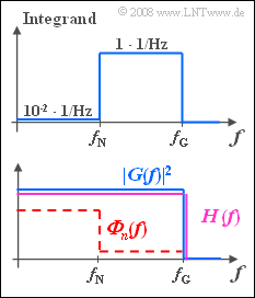
| − | [[File:P_ID648__Sto_Z_5_8_c.png|right|frame| | + | [[File:P_ID648__Sto_Z_5_8_c.png|right|frame|Regarding subtask '''(3)''']] |
| − | '''(3)''' | + | '''(3)''' In general, the SNR for colored interference is: |
:$$\rho _d = 2 \cdot \int_0^\infty \frac{\left| {G(f)} \right|^2 }{{\it \Phi}_n (f)} \, {\rm{d}}f.$$ | :$$\rho _d = 2 \cdot \int_0^\infty \frac{\left| {G(f)} \right|^2 }{{\it \Phi}_n (f)} \, {\rm{d}}f.$$ | ||
| − | * | + | *As can be seen from the accompanying qualitative diagram, the integrand is piecewise constant for the given frequency responses. |
| − | * | + | *Thus, with $f_{\rm G} = 5 \; \rm kHz$ and $f_{\rm N} = f_{\rm G}/2 = 2.5 \; \rm kHz$, we obtain: |
:$$\rho _d = 2 \cdot 2.5\;{\rm{kHz}}\left( { \frac{10^{ - 2}}{\rm{Hz}} + \frac{1}{{{\rm{Hz}}}} } \right) = 5.05 \cdot 10^3 | :$$\rho _d = 2 \cdot 2.5\;{\rm{kHz}}\left( { \frac{10^{ - 2}}{\rm{Hz}} + \frac{1}{{{\rm{Hz}}}} } \right) = 5.05 \cdot 10^3 | ||
\quad \Rightarrow \quad 10\cdot\lg \rho _d \hspace{0.15cm}\underline {= 37.03\;{\rm{dB}}}.$$ | \quad \Rightarrow \quad 10\cdot\lg \rho _d \hspace{0.15cm}\underline {= 37.03\;{\rm{dB}}}.$$ | ||
| Line 94: | Line 94: | ||
'''Interpretation''': | '''Interpretation''': | ||
| − | * | + | *The matched filter frequency response $H_{\rm MF}(f)$ has exactly the same shape as the integrand sketched above. |
| − | * | + | *If the constant $K_{\rm MF}$ is chosen (arbitrarily) so that in the range $f_{\rm N} \le |f| \le f_{\rm G}$ the MF frequency response has the value $1$, then for low frequencies $(|f| < f_{\rm G})$: $H_{\rm MF}(f) = 0.01$. This means: |
| − | :* | + | :*The matched filter favors those frequencies that are only slightly affected by the interference ${\it \Phi}_n(f)$. |
| − | :* | + | :*If instead we would use a filter $H(f)$, which gives equal weight to all frequencies of the wanted signal up to and including $f_{\rm G}$ (purple curve in the sketch below), the following ratios would result: |
::$$d_{\rm S}( {T_{\rm D} } ) = G_0 \cdot 2 \cdot f_{\rm G} = 1\;{\rm{V}}, \quad \sigma _d ^2 = 10^{ - 6} \frac{{{\rm{V}}^{\rm{2}} }}{{{\rm{Hz}}}} \cdot f_{\rm G} + 10^{ - 8} \frac{{{\rm{V}}^{\rm{2}} }}{{{\rm{Hz}}}} \cdot ( {f_{\rm G} - f_{\rm N} } ) = 2.5 \cdot 1.01 \cdot 10^{ - 3} \;{\rm{V}}^{\rm{2}}$$ | ::$$d_{\rm S}( {T_{\rm D} } ) = G_0 \cdot 2 \cdot f_{\rm G} = 1\;{\rm{V}}, \quad \sigma _d ^2 = 10^{ - 6} \frac{{{\rm{V}}^{\rm{2}} }}{{{\rm{Hz}}}} \cdot f_{\rm G} + 10^{ - 8} \frac{{{\rm{V}}^{\rm{2}} }}{{{\rm{Hz}}}} \cdot ( {f_{\rm G} - f_{\rm N} } ) = 2.5 \cdot 1.01 \cdot 10^{ - 3} \;{\rm{V}}^{\rm{2}}$$ | ||
:$$ \Rightarrow \hspace{0.3cm} \rho _d = \frac {d_{\rm S}( {T_{\rm D} } )^2}{\sigma _d ^2} = \frac{1 \;{\rm{V}}^{\rm{2}}}{2.525 \cdot 10^{ - 3} \;{\rm{V}}^{\rm{2}}} = 396 \hspace{0.3cm} \Rightarrow \hspace{0.3cm}10 \cdot {\rm lg} \, \rho _d = 25.98 \, {\rm dB}.$$ | :$$ \Rightarrow \hspace{0.3cm} \rho _d = \frac {d_{\rm S}( {T_{\rm D} } )^2}{\sigma _d ^2} = \frac{1 \;{\rm{V}}^{\rm{2}}}{2.525 \cdot 10^{ - 3} \;{\rm{V}}^{\rm{2}}} = 396 \hspace{0.3cm} \Rightarrow \hspace{0.3cm}10 \cdot {\rm lg} \, \rho _d = 25.98 \, {\rm dB}.$$ | ||
| − | :* | + | :*The signal–to–noise ratio is thus about $11\ \rm dB$ worse than when using the matched filter for colored interference. |
{{ML-Fuß}} | {{ML-Fuß}} | ||
Revision as of 15:57, 26 January 2022

Useful signal spectrum $G(f)$ and PSD ${\it \Phi}_n (f)$ of the interference
The interference power density effective on a system can be assumed to be constant in range:
- $$\it{\Phi} _n \left( f \right) = \left\{ \begin{array}{l} N_0 /2 \\ N_1 /2 \\ \end{array} \right.\quad \begin{array}{*{20}c} \rm{f\ddot{u}r} \\ \rm{f\ddot{u}r} \\\end{array}\quad \begin{array}{*{20}c} {\left| f \right| \le f_{\rm N} ,} \\ {\left| f \right| > f_{\rm N} .} \\\end{array}$$
- Here, let the interference power density $N_1$ in the outer region $|f| > f_{\rm N}$ always be much smaller than $N_0$.
- For example, use the following values:
- $$N_0 = 2 \cdot 10^{ - 6} \;{\rm{V}}^{\rm{2}} /{\rm{Hz}},\quad N_1 = 2 \cdot 10^{ - 8} \;{\rm{V}}^{\rm{2}}/ {\rm{Hz}}.$$
Such an interference signal $n(t)$ occurs, for example, when the dominant interference source contains only components below the frequency limit $f_{\rm N}$. Due to the unavoidable thermal noise, also for $|f| > f_{\rm N}$ the interference power density is ${\it \Phi}_n(f) \ne 0$.
Further, it holds:
- Let the spectrum $G(f)$ of the useful signal also be rectangular according to the above diagram.
- Therefore, the corresponding useful pulse $g(t)$ has the following curve with $\Delta f = 2 \cdot f_{\rm G}$:
- $$g(t) = G_0 \cdot \Delta f \cdot {\mathop{\rm si}\nolimits} \left( {{\rm{\pi }} \cdot \Delta f \cdot t} \right).$$
- Let the reception filter be optimally matched to the useful spectrum $G(f)$ and the interference power density spectrum ${\it \Phi}_n(f)$.
- That is, let $H_{\rm E}(f) = H_{\rm MF}(f)$. Let the detection time be simplified $T_{\rm D} = 0$ (acausal system description).
Notes:
- The exercise belongs to the chapter Matched Filter.
- For numerical calculations always use the numerical values
- $$G_0 = 10^{ - 4} \;{\rm{V/Hz}}{\rm{, }}\quad \Delta f = 10\;{\rm{kHz}}.$$
Questions
Solution
(1) Solutions 1 and 3 are correct:
- For all frequencies $|f| > f_{\rm G}$ at which the useful signal has spectral components $(G_d(f) \ne 0)$, the interference power density spectrum is ${\it}\Phi_n(f) = N_0/2$.
- Thus, the frequency response of the matched filter, assuming $T_{\rm D} = 0$ is:
- $$H_{\rm MF} (f) = K_{\rm MF} \cdot G(f).$$
- In this case, the optimal frequency response $H_{\rm MF}(f)$, just like $G(f)$, is rectangular with width $\Delta f$.
- Thus, for the useful component of the MF output signal holds:
- $$d_{\rm S}(t)\quad \circ\!\!-\!\!\!-\!\!\!-\!\!\bullet\, \quad G(f) \cdot H_{\rm MF} (f).$$
- The product of two rectangular functions of equal width again yields a rectangular function.
- It further follows that the output pulse of the matched filter is also $\rm si$-shaped.
(2) With white noise one obtains:
- $$\rho _d = \frac{1}{N_0 /2}\int_{ - \infty }^{ + \infty } {\left| {G(f)} \right|^2 \, {\rm{d}}f.}$$
- The integral yields the value $G_0^2 \cdot \Delta f$. It follows that:
- $$\rho _d = \frac{G_0 ^2 \cdot \Delta f }{N_0 /2} = \frac{ 10^{ - 8}\,(\rm V/Hz)^2 \;\cdot10^4 \;{\rm{Hz}} }{10^{ - 6}\,\rm V^2/Hz} = 10^2 \quad \Rightarrow \quad 10\lg \rho _d \hspace{0.15cm}\underline { = 20\;{\rm{dB}}}.$$

Regarding subtask (3)
(3) In general, the SNR for colored interference is:
- $$\rho _d = 2 \cdot \int_0^\infty \frac{\left| {G(f)} \right|^2 }{{\it \Phi}_n (f)} \, {\rm{d}}f.$$
- As can be seen from the accompanying qualitative diagram, the integrand is piecewise constant for the given frequency responses.
- Thus, with $f_{\rm G} = 5 \; \rm kHz$ and $f_{\rm N} = f_{\rm G}/2 = 2.5 \; \rm kHz$, we obtain:
- $$\rho _d = 2 \cdot 2.5\;{\rm{kHz}}\left( { \frac{10^{ - 2}}{\rm{Hz}} + \frac{1}{{{\rm{Hz}}}} } \right) = 5.05 \cdot 10^3 \quad \Rightarrow \quad 10\cdot\lg \rho _d \hspace{0.15cm}\underline {= 37.03\;{\rm{dB}}}.$$
Interpretation:
- The matched filter frequency response $H_{\rm MF}(f)$ has exactly the same shape as the integrand sketched above.
- If the constant $K_{\rm MF}$ is chosen (arbitrarily) so that in the range $f_{\rm N} \le |f| \le f_{\rm G}$ the MF frequency response has the value $1$, then for low frequencies $(|f| < f_{\rm G})$: $H_{\rm MF}(f) = 0.01$. This means:
- The matched filter favors those frequencies that are only slightly affected by the interference ${\it \Phi}_n(f)$.
- If instead we would use a filter $H(f)$, which gives equal weight to all frequencies of the wanted signal up to and including $f_{\rm G}$ (purple curve in the sketch below), the following ratios would result:
- $$d_{\rm S}( {T_{\rm D} } ) = G_0 \cdot 2 \cdot f_{\rm G} = 1\;{\rm{V}}, \quad \sigma _d ^2 = 10^{ - 6} \frac{{{\rm{V}}^{\rm{2}} }}{{{\rm{Hz}}}} \cdot f_{\rm G} + 10^{ - 8} \frac{{{\rm{V}}^{\rm{2}} }}{{{\rm{Hz}}}} \cdot ( {f_{\rm G} - f_{\rm N} } ) = 2.5 \cdot 1.01 \cdot 10^{ - 3} \;{\rm{V}}^{\rm{2}}$$
- $$ \Rightarrow \hspace{0.3cm} \rho _d = \frac {d_{\rm S}( {T_{\rm D} } )^2}{\sigma _d ^2} = \frac{1 \;{\rm{V}}^{\rm{2}}}{2.525 \cdot 10^{ - 3} \;{\rm{V}}^{\rm{2}}} = 396 \hspace{0.3cm} \Rightarrow \hspace{0.3cm}10 \cdot {\rm lg} \, \rho _d = 25.98 \, {\rm dB}.$$
- The signal–to–noise ratio is thus about $11\ \rm dB$ worse than when using the matched filter for colored interference.