Difference between revisions of "Aufgaben:Exercise 3.5Z: Phase Modulation of a Trapezoidal Signal"
m |
m |
||
| Line 3: | Line 3: | ||
}} | }} | ||
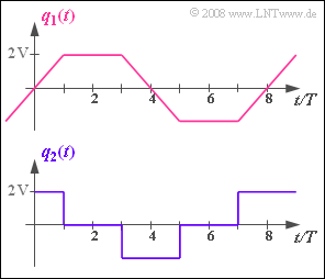
| − | [[File:P_ID1100__Mod_Z_3_5.png|right|frame| | + | [[File:P_ID1100__Mod_Z_3_5.png|right|frame|Trapezoidal and rectangular signals]] |
A phase modulator with input signal $q_1(t)$ a modulated signal $s(t)$ at the output are described as follows: | A phase modulator with input signal $q_1(t)$ a modulated signal $s(t)$ at the output are described as follows: | ||
:$$s(t) = A_{\rm T} \cdot \cos \hspace{-0.05cm}\big[\psi(t) \big ]= | :$$s(t) = A_{\rm T} \cdot \cos \hspace{-0.05cm}\big[\psi(t) \big ]= | ||
Revision as of 13:57, 17 March 2022
A phase modulator with input signal $q_1(t)$ a modulated signal $s(t)$ at the output are described as follows:
- $$s(t) = A_{\rm T} \cdot \cos \hspace{-0.05cm}\big[\psi(t) \big ]= A_{\rm T} \cdot \cos \hspace{-0.05cm}\big[\omega_{\rm T} \cdot t + K_{\rm PM} \cdot q_1(t) \big ] \hspace{0.05cm}.$$
- The carrier angular frequency is $ω_{\rm T} = 2π · 10^5 \cdot {1}/{\rm s}$.
- The instantaneous angular frequency $ω_{\rm A}(t)$ is equal to the derivative of the angle function $ψ(t)$ with respect to time.
- The instantaneous frequency is thus $f_{\rm A}(t) = ω_{\rm A}(t)/2π$.
The trapezoidal signal $q_1(t)$ is applied as a test signal, where the nominated time duration is $T = 10 \ \rm µ s$ .
The same modulated signal $s(t)$ would result from a frequency modulator with the angular function
- $$\psi(t) = \omega_{\rm T} \cdot t + K_{\rm FM} \cdot \int q_2(t)\hspace{0.15cm}{\rm d}t$$
if the rectangular source signal $q_2(t)$ is applied according to the lower plot.
Hints:
- This exercise belongs to the chapter Frequency Modulation.
- Reference is also made to the chapter Phase Modulation.
Questions
Solution
- $$ \phi_{\rm max} = K_{\rm PM} \cdot 2\,{\rm V} = 3\,{\rm rad}\hspace{0.3cm}\Rightarrow \hspace{0.3cm} K_{\rm PM} \hspace{0.15cm}\underline {= 1.5\,{\rm V^{-1}}} \hspace{0.05cm}.$$
(2) In the range $0 < t < T$ , the angular function can be represented as follows:
- $$ \psi(t) = \omega_{\rm T} \cdot t + K_{\rm PM} \cdot 2\,{\rm V} \cdot {t}/{T}\hspace{0.05cm}.$$
- The instantaneous angular frequency $ω_{\rm A}(t)$ or the instantaneous frequency $f_{\rm A}(t)$ the following holds:
- $$\omega_{\rm A}(t) = \frac{{\rm d}\hspace{0.03cm}\psi(t)}{{\rm d}t}= \omega_{\rm T} + K_{\rm PM} \cdot \frac{2\,{\rm V}}{10\,{\rm µ s}}\hspace{0.05cm} \hspace{0.3cm} \Rightarrow \hspace{0.3cm} f_{\rm A}(t) = f_{\rm T} + \frac{1.5\,{\rm V}^{-1}}{2 \pi} \cdot 2 \cdot 10^5 \rm {V}/{ s} = 100\,{\rm kHz}+ 47.7\,{\rm kHz}= 147.7\,{\rm kHz}\hspace{0.05cm}.$$
- The instantaneous frequency is constant, sonbsp; $f_\text{A, min} = f_\text{A, max}\hspace{0.15cm}\underline{ = 147.7 \ \rm kHz}$ holds.
(3) Due to the constant source signal, the derivative is zero throughout the time interval $T < t < 3T$ under consideration, so the instantaneous frequency is equal to the carrier frequency:
- $$f_{\rm A, \hspace{0.05cm} min} =f_{\rm A, \hspace{0.05cm} max} =f_{\rm T} \hspace{0.15cm}\underline {= 100\,{\rm kHz}}\hspace{0.05cm}.$$
(4) The linear decay of $q_1(t)$ in the time interval $3T < t < 5T$ with slope as calculated in (2) leads to the result:
- $$f_{\rm A, \hspace{0.05cm} min} =f_{\rm A, \hspace{0.05cm} max} =f_{\rm T} - 47.7\,{\rm kHz} \hspace{0.15cm}\underline {= 52.3\,{\rm kHz}}\hspace{0.05cm}.$$
(5) By differentiation, we arrive at the instantaneous angular frequency:
- $$ \omega_{\rm A}(t) = \omega_{\rm T} + K_{\rm FM} \cdot q_2(t) \Rightarrow \hspace{0.3cm} f_{\rm A}(t) = f_{\rm T}+\frac{ K_{\rm FM}}{2 \pi} \cdot q_2(t)\hspace{0.05cm}.$$
- Using the result from (2) , we get:
- $$\frac{ K_{\rm FM}}{2 \pi} \cdot 2\,{\rm V} = \frac{ 3 \cdot 10^5}{2 \pi} \cdot {\rm s^{-1}}\hspace{0.3cm}\Rightarrow \hspace{0.3cm} K_{\rm FM} \hspace{0.15cm}\underline {= 1.5 \cdot 10^5 \hspace{0.15cm}{\rm V^{-1}}{\rm s^{-1}}}\hspace{0.05cm}.$$
