Difference between revisions of "Channel Coding/Error Probability and Application Areas"
| Line 183: | Line 183: | ||
[[Aufgaben:Exercise_2.16:_Bounded_Distance_Decoding:_Decision_Regions|Exercise 2.16: Bounded Distance Decoding: Decision Regions]] | [[Aufgaben:Exercise_2.16:_Bounded_Distance_Decoding:_Decision_Regions|Exercise 2.16: Bounded Distance Decoding: Decision Regions]] | ||
| − | == | + | ==References== |
<references/> | <references/> | ||
{{Display}} | {{Display}} | ||
Revision as of 20:50, 28 September 2022
Contents
Block error probability for RSC and BDD
For error probability calculation we start from the same block diagram as in chapter "Error correction according to Reed-Solomon coding" , but here we choose the codeword estimator $(\underline {y} → \underline {z})$ to "Bounded Distance Decoding" $\rm (BDD)$ . For Maximum Likelihood Decoding the results are slightly better.
Let the block error probability be defined as follows:
- \[{ \rm Pr(Block\:error)} = { \rm Pr}( \underline{v} \ne \underline{u})= { \rm Pr}( \underline{z} \ne \underline{c}) = { \rm Pr}( f >t) \hspace{0.05cm}.\]
Due to the BDD assumption, the same simple result is obtained as for the binary block codes, namely the probability that the number $f$ of errors in the block (received word) is greater than the correctability $t$ of the code.
Since for the random variable $f$ (number of errors) there is a "Binomial distribution" in the range $0 ≤ f ≤ n$ we obtain:
- \[{\rm Pr(Block\:error)} = \sum_{f = t + 1}^{n} {n \choose f} \cdot {\varepsilon_{\rm S}}^f \cdot (1 - \varepsilon_{\rm S})^{n-f} \hspace{0.05cm}.\]
But while in the first main chapter always $c_i ∈ \rm GF(2)$ has applied and thus the $f$ transmission errors were in each case bit errors, in Reed– Solomon coding under a transmission error $(y_i \ne c_i)$ because of $c_i ∈ {\rm GF}(2^m)$ and $y_i ∈ {\rm GF}(2^m)$ a symbol error.
This results in the following differences:
- The discrete channel model used to describe the binary block codes is the "Binary Symmetric Channel" (BSC). Each bit $c_i$ of a codeword is corrupted with probability $\varepsilon$ and correctly transmitted with probability $1-\varepsilon$ $(y_i = c_i)$.
- For Reed–Solomon–coding, one must replace the BSC model with the $m$ BSC channel model. A symbol $c_i$ is corrupted with probability $\varepsilon_{\rm S}$ into another symbol $y_i$ (no matter which one) and arrives with probability $1-\varepsilon_{\rm S}$ uncorrupted at the receiver.
$\text{Example 1:}$ We start from the BSC parameter $\varepsilon = 0.1$ and consider Reed–Solomon code symbols $c_i ∈ {\rm GF}(2^8)$ ⇒ $m = 8$, $q = 256$, $n = 255$.
For a symbol corruption $(y_i \ne c_i)$ already one wrong bit is sufficient. Or expressed differently: If $y_i = c_i$ is to be valid, then all $m = 8$ bits of the code symbol must be transmitted correctly:
- \[1 - \varepsilon_{\rm S} = (1 - \varepsilon)^m = 0.9^8 \approx 0.43 \hspace{0.05cm}.\]
- Thus, for the 8 BSC model, the falsification probability $\varepsilon_{\rm S} ≈ 0.57$.
- With the further assumption that the falsification of $c_i = \beta$ into any other symbol $y_i = \gamma \ne \beta$ is equally likely, we obtain:
- $${\rm Pr}(y_i = \gamma\hspace{0.05cm}\vert \hspace{0.05cm}c_i = \beta = 0.57/255 ≈ 0.223\%.$$
Application of Reed–Solomon coding for binary channels
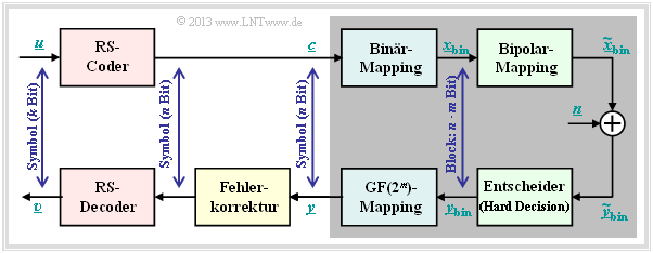
The prerequisites for the following calculation of the block error probability of a system with Reed–Solomon coding and conversion to binary symbols are summarized in the diagram:
- Assume a $(n, k)$ Reed–Solomon coding with symbols of $c_i ∈ {\rm GF}(2^m)$. The smaller the code rate $R=k/m$ is, the less information can be transmitted at a fixed data rate.
- Each symbol is represented by $m$ bits in binary ⇒ binary mapping. A block $($code word $\underline {c} )$ thus consists of $n$ symbols or of $n \cdot m$ binary characters (bits) combined in $\underline {c}_{\rm bin} $ .
- In addition, the "AWGN Channel", identified by the parameter $E_{\rm B}/N_0 $ is assumed. According to this channel model the transmission happens bipolar: "0" ↔ $+1$ and "1" ↔ $-1$.
- The receiver makes hard decisions on bit level. Before decoding including error correction, the binary symbols are converted back to ${\rm GF}(2^m)$ symbols.
The equation given on the last page (valid for Bounded Distance Decoding),
- \[{\rm Pr(Block\:error)} = \sum_{f = t + 1}^{n} {n \choose f} \cdot {\varepsilon_{\rm S}}^f \cdot (1 - \varepsilon_{\rm S})^{n-f} \hspace{0.05cm},\]
is based on the $m$ BSC channel. Starting from the AWGN–channel (Additive White Gaussian Noise ), the "complementary Gaussian error integral" ${\rm Q}(x)$ to the BSC parameter
- \[\varepsilon = {\rm Q} \big (\sqrt{2 \cdot E_{\rm S}/N_0} \big ) = {\rm Q} \big (\sqrt{2 \cdot R \cdot E_{\rm B}/N_0} \big ) \hspace{0.05cm},\]
comes from this to the symbol-level corruption probability $\varepsilon_{\rm S}$:
- \[\varepsilon_{\rm S} = 1 - (1 - \varepsilon)^m \hspace{0.05cm}.\]
$\text{Example 2:}$ One gets with
- $R=k/n = 239/255 = 0.9373$,
- $10 \cdot \lg \ E_{\rm B}/N_0 = 7 \, \rm dB$ ⇒ $E_{\rm B}/N_0 ≈ 5$, und
- $n = 2^8-1$ ⇒ $m = 8$
for the parameters $\varepsilon$ of the BSC model and $\varepsilon_{\rm S}$ of the 8 BSC model the following numerical values:
- $$\varepsilon = {\rm Q} \big (\sqrt{2 \cdot 0.9373 \cdot 5} \big ) = {\rm Q} \big (3.06\big ) \approx 1.1 \cdot 10^{-3}=0.11 \cdot \%$$
- $$\Rightarrow\hspace{0.3cm} \varepsilon_{\rm S} = 1 - (1 - 1.1 \cdot 10^{-3})^8 = 1 - 0.9989^8 = 1 - 0.9912 \approx 0.88 \cdot \% \hspace{0.2cm}(\approx 8 \cdot \varepsilon)\hspace{0.05cm}.$$
So every single symbol is transmitted with more than $99$ percent probability without errors.
BER of Reed–Solomon coding for binary channels
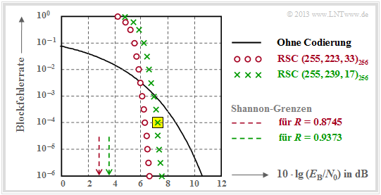
The following graph shows the block error probabilities given in [Liv10][1] given block error probabilities as a function of the AWGN quotient $10 \cdot \lg \ E_{\rm B}/N_0$.
Shown are the calculated curves ${ \rm Pr}( \underline{v} \ne \underline{u})$ for two different Reed–Solomon–codes corresponding to the Deep Space Standards according to CCSDS (Consultative Committee for Space Data Systems), namely
- the $\text{RSC (255, 239, 17)}_{256}$ with $R=0.9373$, which can correct up to $t = 8$ errors, and
- the $\text{RSC (255, 223, 33)}_{256}$ with higher correction capability $(t = 16)$ due to smaller code rate.
Hint: You are to perform the calculation only hinted at below in the "Exercise 2.15" for the $\text{RSC (7, 3, 5)}_{8}$ – thus for somewhat clearer parameters – completely.
We analyze the point highlighted in yellow in the graph, valid for the $\text{RSC (255, 239, 17)}_{256}$ and $10 \cdot \lg \ E_{\rm B}/N_0 = 7.1 \,\rm dB$ ⇒ $\varepsilon = 0.007$. The corresponding block error probability results according to the diagram to
- \[{\rm Pr(Block\:error)} = \sum_{f =9}^{255} {255 \choose f} \cdot {\varepsilon_{\rm S}}^f \cdot (1 - \varepsilon_{\rm S})^{255-f}\approx 10^{-4} \hspace{0.05cm}.\]
Dominant here is the first term $($for $f=9)$, which already accounts for about $80\%$ :
- \[{255 \choose 9} \approx 1.1 \cdot 10^{16}\hspace{0.05cm},\hspace{0.15cm} \varepsilon_{\rm S}^9 \approx 4 \cdot 10^{-20}\hspace{0.05cm},\hspace{0.15cm} (1 -\varepsilon_{\rm S})^{246} \approx 0.18 \hspace{0.15cm} \Rightarrow \hspace{0.15cm} {\rm Pr}(f = 9) \approx 8 \cdot 10^{-5} \hspace{0.05cm}.\]
This should be taken as proof that one may stop the summation already after a few terms.
The results shown in the graph can be summarized as follows:
- For small $E_{\rm B}/N_0$ (of the AWGN channel), the Reed–Solomon codes are completely unsuitable. Both codes are for $10 \cdot \lg \ E_{\rm B}/N_0 < 6 \,\rm dB$ above the (black) comparison curve for uncoded transmission.
- The calculation for the $\text{RSC (255, 223, 33)}_{256}$ differs from the above calculation only in the lower summation limit $(f_{\rm min} = 17)$ and by a slightly larger $\varepsilon_{\rm S}$ $($because $R = 0.8745)$.
- This "red" code $($with $t = 16)$ is better for $\rm BER = 10^{-6}$ also only by about $1 \, \rm dB$ than the code marked by green crosses with $t = 8$. So the results of both codes are rather disappointing.
$\text{Conclusion:}$
- Reed–Solomon codes are not very good at the memoryless binary channel (AWGN channel). Both codes are more than $4 \, \rm dB$ away from the information-theoretical "Shannon limit" .
- Reed–Solomon codes on the other hand are very effective with so-called "Burst Error Channels". They are therefore mainly used for fading channels, memory systems, etc.
- The Reed–Solomon codes are not perfect. The consequences of this are covered in the "Exercise 2.16" ..
Typical applications with Reed–Solomon coding
Reed–Solomon coding is often applied according to the diagram together with an inner code in cascaded form.
- The inner code is almost always a binary code and in satellite– and mobile communications often a convolutional code.
- If one wishes to study only Reed–Solomon coding/decoding, one replaces the grayed components in a simulation with a single block called a "super channel".
Such a concatenated coding system is particularly efficient if an interleaver is connected between the two coders to further relax burst errors.
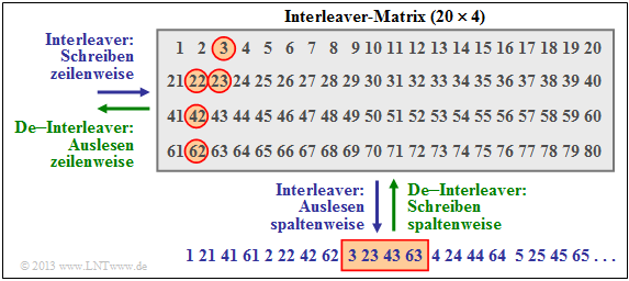
$\text{Example 3:}$ The diagram shows an example of such an interleaver, where we restrict ourselves to a $20 × 4$ matrix. In practice, these matrices are significantly larger.
The interleaver is written row by row and read out column by column (blue label). With the de–interleaver (green label) the sequence is exactly the other way round.
- The Reed–Solomon symbols are therefore not forwarded to the inner coder consecutively, but according to the specified sequence as symbol 1, 21, 41, 61, 2, 22, etc. .
- On the channel a contiguous area (here the symbols 42, 62, 3, 23, 43, 63, 4, 24 ⇒ around the rectangle outlined in red below) is destroyed, for example by a scratch on the channel "storage medium".
- After de–interleaving, the symbol sequence is again 1, 2, 3, ... You can see from the red outlined circles that now this burst error has been largely "broken up".
$\text{Example 4:}$ A very widely used application of Reed–Solomon coding – and also the most commercially successful – is the Compact Disc $\rm (CD)$, whose error correction mechanism has already been described in the "introduction chapter" of this book. Here the inner code is also a Reed–Solomon code, and the concatenated coding system can be described as follows:
- Both channels of the stereo–audio signal are sampled at $\text{44.1 kHz}$ each and every sample is digitally represented at $32$ bits (four bytes).
- The grouping of six samples results in a frame $(192$ Bit$)$ and thus $24$ code symbols from the Galois field $\rm GF(2^8)$. Each code symbol thus corresponds to exactly one byte.
- The first Reed–Solomon code with rate $R_1 = 24/28$ returns $28$ bytes, which are fed to an interleaver of size $28 × 109$ bytes. The readout is done (complicated) diagonally.
- The interleaver distributes contiguous bytes over a large area of the entire disc. This "resolves" so-called bursts caused by scratches on the $\rm CD$ for example.
- Together with the second Reed–Solomon code $($rate $R_2 = 28/32)$ gives a total rate of $R = (24/28) · (28/32) = 3/4$. Both codes can each $t = 2$ correct symbol errors.
- The two component codes $\text{RSC (28, 24, 5)}$ and $\text{RSC (32, 28, 5)}$ are each based on the Galois field $\rm GF(2^8)$, which would actually mean code length $n = 255$ .
- The shorter component codes needed here result from the $\text{RSC (255, 251, 5)}_{256}$ by shortening ⇒ see "Exercise 1.9Z". However, this measure does not change the minimum distance $d_{\rm min}= 5$ .
- With the subsequent "Eight to Fourteen Modulation" and further control symbols, one finally arrives at the final code rate $ R = 192/588 ≈ 0.326$ of CD data compression.
On the page "Slit CD" you can see for yourself the correction capabilities of this cross–interleaved Reed–Solomon coding with the help of an audio example, but you can also see its limitations
.
Exercises for the chapter
Exercise 2.15: Block Error Probability with AWGN
Exercise 2.15Z: Block Error Probability once more
Exercise 2.16: Bounded Distance Decoding: Decision Regions
References
- ↑ Liva, G.: Channel Coding. Lecture Notes, Chair of Communications Engineering, TU Munich and DLR Oberpfaffenhofen, 2010.


