Difference between revisions of "Exercise 2.4Z: Characteristics Measurement"
| Line 19: | Line 19: | ||
For the subtasks '''(3)''' and '''(4)''' let the input signal $x(t)$ be a harmonic oscillation because only for such an oscillation a distortion factor can be specified. | For the subtasks '''(3)''' and '''(4)''' let the input signal $x(t)$ be a harmonic oscillation because only for such an oscillation a distortion factor can be specified. | ||
| − | + | In contrast, a triangular pulse with amplitude $A_x = 3 \ {\rm V}$ and the one-sided pulse duration $T_x = 2 \ {\rm ms}$ is considered for the subtask '''(5)''' : | |
:$$x(t) = A_x \cdot ( 1 - {|t|}/{T_x}) $$ | :$$x(t) = A_x \cdot ( 1 - {|t|}/{T_x}) $$ | ||
Revision as of 19:55, 15 September 2021
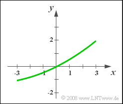
It is known that the characteristic curve can be represented as follows for a nonlinear system:
- $$y(t) = c_1 \cdot x(t) + c_2 \cdot x^2(t).$$
Since the distortions are nonlinear no frequency response $H(f)$ can be given.
To determine the dimensionless coefficient $c_1$ as well as the quadratic coefficient $c_2$ different rectangular pulses $x(t)$ – characterized by the amplitude $A_x$ and width $T_x$ – are now applied to the input and the pulse amplitude $A_y$ at the output is measured in each case.
The first three trials generate the following values:
- $A_x = 1 \ {\rm V}, \; \; T_x = 8 \ {\rm ms}$ : $A_y = 0.55 \ {\rm V}$,
- $A_x = 2 \ {\rm V}, \; \; T_x = 4 \ {\rm ms}$ : $A_y = 1.20 \ {\rm V}$,
- $A_x = 3 \ {\rm V}, \; \; T_x = 2 \ {\rm ms}$ : $A_y = 1.95 \ {\rm V}$.
For the subtasks (3) and (4) let the input signal $x(t)$ be a harmonic oscillation because only for such an oscillation a distortion factor can be specified.
In contrast, a triangular pulse with amplitude $A_x = 3 \ {\rm V}$ and the one-sided pulse duration $T_x = 2 \ {\rm ms}$ is considered for the subtask (5) :
- $$x(t) = A_x \cdot ( 1 - {|t|}/{T_x}) $$
Please note:
- The task belongs to the chapter Nonlinear Distortion.
- The following abbreviations are used in the formulation of the questions:
- $$y_1(t) = c_1 \cdot x(t), \hspace{0.5cm} y_2(t) = c_2 \cdot x^2(t).$$
Questions
Solution
- Ist der Eingangsimpuls $x(t)$ rechteckförmig, so ist auch $x^2(t)$ ein Rechteck mit Höhe $A_x^2$ zwischen $0$ und $T_x$; außerhalb Null.
- Auch das gesamte Ausgangssignal $y(t)$ ist somit rechteckförmig mit der Amplitude
- $$A_y= c_1 \cdot A_x + c_2 \cdot A_x^2 .$$
- Für die Impulsdauer gilt: $T_y = T_x$.
(2) Mit den beiden ersten Parametersätzen kann folgendes lineares Gleichungssystem angegeben werden:
- $$c_1 \cdot 1\,{\rm V} + c_2 \cdot (1\,{\rm V})^2 = 0.55\,{\rm V},$$
- $$c_1 \cdot 2\,{\rm V} + c_2 \cdot (2\,{\rm V})^2 = 1.20\,{\rm V}.\hspace{0.05cm}$$
- Durch Multiplikation der ersten Gleichung mit $-2$ und Addition der beiden Gleichungen erhält man:
- $$c_2 \cdot 2\,{\rm V}^2 = 0.1\,{\rm V} \hspace{0.3cm}\Rightarrow \hspace{0.3cm} c_2 \hspace{0.15cm}\underline{= 0.05\cdot{1/\rm V}}.$$
- Der Linearkoeffizient ist somit $c_1 \hspace{0.15cm}\underline{= 0.5}.$
- Der dritte Parametersatz kann genutzt werden, um das Ergebnis zu kontrollieren:
- $$c_1 \cdot 3\,{\rm V} + c_2 \cdot (3\,{\rm V})^2 = 0.5 \cdot 3\,{\rm V}+ 0.05 \ {1}/{\rm V}\cdot 9\,{\rm V}^2 = 1.95\,{\rm V}.$$
(3) Die Angabe eines Klirrfaktors bedingt die Verwendung einer harmonischen Schwingung am Eingang.
- Ist $X_+(f) = 1 \ {\rm V} \cdot \delta (f - f_0)$, so lautet das Spektrum des analytischen Signals am Ausgang:
- $$ Y_{+}(f)={c_2}/{2}\cdot A_x^2 \cdot \delta(f) + c_1\cdot A_x \cdot \delta(f- f_0)+ {c_2}/{2}\cdot A_x^2 \cdot \delta(f- 2 f_0). $$
- Die Diracfunktion bei $f = 0$ folgt aus der trigonometrischen Umformung $\cos^2(\alpha) = 1/2 + 1/2 \cdot \cos(\alpha).$
- Mit $A_1 = c_1 \cdot A_x = 0.5 \ {\rm V} $ und $A_2 = (c_2/2) \cdot A_x^2 = 0.025 \ {\rm V}^2 $ ergibt sich somit für den Klirrfaktor:
- $$K= \frac{A_2}{A_1}= \frac{c_2/2 \cdot A_x}{c_1 }= \frac{0.025}{0.5} \hspace{0.15cm}\underline{= 5 \%}.$$
(4) Entsprechend der Musterlösung zur letzten Teilaufgabe ist $K$ proportional zu $A_x$. Deshalb erhält man nun $K \hspace{0.15cm}\underline{= 15 \%}.$
(5) Nun lautet das Ausgangssignal:
- $$y(t)= c_1\cdot A_x \cdot \left( 1 - {|\hspace{0.05cm}t\hspace{0.05cm}|}/{T_x}\right) +\hspace{0.1cm} {c_2}\cdot A_x^2 \cdot \left( 1 - {|\hspace{0.05cm}t\hspace{0.05cm}|}/{T_x}\right)^2.$$
- Zum Zeitpunkt $t = 0$ bzw. $t = T_x/2$ treten folgende Werte auf:
- $$y(t=0) = c_1\cdot A_x + {c_2}\cdot A_x^2 \hspace{0.15cm}\underline{= 1.95\,{\rm V}},$$
- $$y(t=T_x/2) = c_1\cdot A_x \cdot {1}/{2} + \hspace{0.1cm}{c_2}\cdot A_x^2 \cdot {1}/{4}= 0.75\,{\rm V}+ 0.1125\,{\rm V} \hspace{0.15cm}\underline{ = 0.8625\,{\rm V}}.$$
