Difference between revisions of "Aufgaben:Exercise 4.14: 8-PSK and 16-PSK"
| Line 1: | Line 1: | ||
| − | {{quiz-Header|Buchseite= | + | {{quiz-Header|Buchseite=Digital_Signal_Transmission/Carrier_Frequency_Systems_with_Coherent_Demodulation}} |
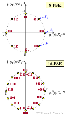
| − | [[File:P_ID2067__Dig_A_4_14.png|right|frame| | + | [[File:P_ID2067__Dig_A_4_14.png|right|frame|Signal space constellations <br>of the 8-PSK and 16-PSK]] |
| − | + | Now a signal set $\{s_i(t)\}$ is considered, which is limited to the time domain $0 ≤ t ≤ T$. The index $i$ runs through the values $0, \ \text{...} \ , M-1$: | |
:$$s_i(t) = A \cdot \cos \left ( 2\pi f_{\rm T}t + { 2\pi }/{ M} \cdot i \right ) \hspace{0.05cm}.$$ | :$$s_i(t) = A \cdot \cos \left ( 2\pi f_{\rm T}t + { 2\pi }/{ M} \cdot i \right ) \hspace{0.05cm}.$$ | ||
| − | + | This is a <i>phase modulation</i> with $M$ signal shapes. This modulation process is also called <b><i>M</i>–PSK</b>. $M$ is usually a power of two. | |
| − | + | The graphic shows the signal space constellation for $M = 8$ (top) and $M = 16$ (bottom). All signal space points have equal energy $||\boldsymbol{s}_i||^2 = E_{\rm S}$ ("mean symbol energy"). | |
| − | + | The exact calculation of the error probability is difficult for $M ≠ 2$. However, the so-called <i>Union Bound</i> can always be given as an upper bound for the symbol error probability $(p_{\rm UB} ≥ p_{\rm S})$: | |
:$$ p_{\rm UB} = 2 \cdot {\rm Q} \left ( \frac{ d/2}{ \sigma_n}\right ) = 2 \cdot {\rm Q} \left (\sqrt{ \frac{ d^2}{ 2 N_0}}\right ) \hspace{0.05cm}.$$ | :$$ p_{\rm UB} = 2 \cdot {\rm Q} \left ( \frac{ d/2}{ \sigma_n}\right ) = 2 \cdot {\rm Q} \left (\sqrt{ \frac{ d^2}{ 2 N_0}}\right ) \hspace{0.05cm}.$$ | ||
| − | + | The following quantities are used here: | |
| − | * $d$ | + | * $d$ is the distance between two neighboring points, for example between $\boldsymbol{s}_0$ and $\boldsymbol{s}_1$. If the decision boundary is exactly centered perpendicular to the line connecting $\boldsymbol{s}_0$ and $\boldsymbol{s}_1$, then $d/2$ is the distance of $\boldsymbol{s}_0$ or $\boldsymbol{s}_1$ from this decision boundary. |
| − | * | + | * The variance of the AWGN noise is $\sigma_n^2 = N_0/2$. |
| − | * | + | * The factor of $2$ in the above limit takes into account that for $M > 2$ each signal space point can be falsified in two directions, for example, for the 8–PSK the symbol $\boldsymbol{s}_0$ into the symbol $\boldsymbol{s}_1$ or into the symbol $\boldsymbol{s}_7$. |
| − | * ${\rm Q}(x)$ | + | * ${\rm Q}(x)$ is the complementary Gaussian error function for which the following approximation holds: |
:$${\rm Q}(x) \approx \frac{1}{\sqrt{2\pi} \cdot x} \cdot {\rm e}^{-x^2/2} | :$${\rm Q}(x) \approx \frac{1}{\sqrt{2\pi} \cdot x} \cdot {\rm e}^{-x^2/2} | ||
\hspace{0.05cm}.$$ | \hspace{0.05cm}.$$ | ||
| − | + | The last subtask deals with the bit error probability. For this, the following bound was given in the [[Digital_Signal_Transmission/Carrier_Frequency_Systems_with_Coherent_Demodulation| "theory section"]] under the assumption of a <i>Gray code</i>: | |
:$$p_{\rm B} \le \frac{2}{{\rm log_2} \hspace{0.05cm}(M)} \cdot {\rm Q} \left ( \sqrt{{\rm log_2} \hspace{0.05cm}(M)} \cdot \sin ({ \pi}/{ M}) \cdot \sqrt{ { {2E_{\rm B}}}/{ N_0} }\right ) | :$$p_{\rm B} \le \frac{2}{{\rm log_2} \hspace{0.05cm}(M)} \cdot {\rm Q} \left ( \sqrt{{\rm log_2} \hspace{0.05cm}(M)} \cdot \sin ({ \pi}/{ M}) \cdot \sqrt{ { {2E_{\rm B}}}/{ N_0} }\right ) | ||
\hspace{0.05cm}.$$ | \hspace{0.05cm}.$$ | ||
| Line 34: | Line 34: | ||
''Hinweise:'' | ''Hinweise:'' | ||
| − | * Die Aufgabe gehört zum Themengebiet des Kapitels [[ | + | * Die Aufgabe gehört zum Themengebiet des Kapitels [[Digital_Signal_Transmission/Carrier_Frequency_Systems_with_Coherent_Demodulation|"Carrier Frequency Systems with Coherent Demodulation"]]. |
*Bezug genommen eird insbesondere auf die Seite [[Digitalsignal%C3%BCbertragung/Tr%C3%A4gerfrequenzsysteme_mit_koh%C3%A4renter_Demodulation#Mehrstufiges_Phase.E2.80.93Shift_Keying_.28M.E2.80.93PSK.29| Mehrstufiges ''Phase Shift Keying'']]. | *Bezug genommen eird insbesondere auf die Seite [[Digitalsignal%C3%BCbertragung/Tr%C3%A4gerfrequenzsysteme_mit_koh%C3%A4renter_Demodulation#Mehrstufiges_Phase.E2.80.93Shift_Keying_.28M.E2.80.93PSK.29| Mehrstufiges ''Phase Shift Keying'']]. | ||
* Die Zuordnung der 8 bzw. 16 Symbole zu Binärfolgen der Länge 3 bzw. 4 nach der Graycodierung kann der Grafik entnommen werden (rote Beschriftung). | * Die Zuordnung der 8 bzw. 16 Symbole zu Binärfolgen der Länge 3 bzw. 4 nach der Graycodierung kann der Grafik entnommen werden (rote Beschriftung). | ||
Revision as of 13:05, 12 August 2022
Now a signal set $\{s_i(t)\}$ is considered, which is limited to the time domain $0 ≤ t ≤ T$. The index $i$ runs through the values $0, \ \text{...} \ , M-1$:
- $$s_i(t) = A \cdot \cos \left ( 2\pi f_{\rm T}t + { 2\pi }/{ M} \cdot i \right ) \hspace{0.05cm}.$$
This is a phase modulation with $M$ signal shapes. This modulation process is also called M–PSK. $M$ is usually a power of two.
The graphic shows the signal space constellation for $M = 8$ (top) and $M = 16$ (bottom). All signal space points have equal energy $||\boldsymbol{s}_i||^2 = E_{\rm S}$ ("mean symbol energy").
The exact calculation of the error probability is difficult for $M ≠ 2$. However, the so-called Union Bound can always be given as an upper bound for the symbol error probability $(p_{\rm UB} ≥ p_{\rm S})$:
- $$ p_{\rm UB} = 2 \cdot {\rm Q} \left ( \frac{ d/2}{ \sigma_n}\right ) = 2 \cdot {\rm Q} \left (\sqrt{ \frac{ d^2}{ 2 N_0}}\right ) \hspace{0.05cm}.$$
The following quantities are used here:
- $d$ is the distance between two neighboring points, for example between $\boldsymbol{s}_0$ and $\boldsymbol{s}_1$. If the decision boundary is exactly centered perpendicular to the line connecting $\boldsymbol{s}_0$ and $\boldsymbol{s}_1$, then $d/2$ is the distance of $\boldsymbol{s}_0$ or $\boldsymbol{s}_1$ from this decision boundary.
- The variance of the AWGN noise is $\sigma_n^2 = N_0/2$.
- The factor of $2$ in the above limit takes into account that for $M > 2$ each signal space point can be falsified in two directions, for example, for the 8–PSK the symbol $\boldsymbol{s}_0$ into the symbol $\boldsymbol{s}_1$ or into the symbol $\boldsymbol{s}_7$.
- ${\rm Q}(x)$ is the complementary Gaussian error function for which the following approximation holds:
- $${\rm Q}(x) \approx \frac{1}{\sqrt{2\pi} \cdot x} \cdot {\rm e}^{-x^2/2} \hspace{0.05cm}.$$
The last subtask deals with the bit error probability. For this, the following bound was given in the "theory section" under the assumption of a Gray code:
- $$p_{\rm B} \le \frac{2}{{\rm log_2} \hspace{0.05cm}(M)} \cdot {\rm Q} \left ( \sqrt{{\rm log_2} \hspace{0.05cm}(M)} \cdot \sin ({ \pi}/{ M}) \cdot \sqrt{ { {2E_{\rm B}}}/{ N_0} }\right ) \hspace{0.05cm}.$$
Diese Gleichung ist allerdings nur für $M > 4$ anzuwenden. Dagegen ergibt sich die exakte Lösung
- für $M = 2$ aus der Identität mit der BPSK, und
- für $M = 4$ aus der Tatsache, dass die 4–PSK mit der 4–QAM identisch ist:
- $$p_{\rm B} ={\rm Q} \left ( \sqrt{ { {2E_{\rm B}}}/{ N_0} }\right ) \hspace{0.05cm}.$$
Hinweise:
- Die Aufgabe gehört zum Themengebiet des Kapitels "Carrier Frequency Systems with Coherent Demodulation".
- Bezug genommen eird insbesondere auf die Seite Mehrstufiges Phase Shift Keying.
- Die Zuordnung der 8 bzw. 16 Symbole zu Binärfolgen der Länge 3 bzw. 4 nach der Graycodierung kann der Grafik entnommen werden (rote Beschriftung).
- Bei der Lösung der Aufgabe können Sie folgende Gleichungen verwenden:
- $$\cos(\alpha + \beta) \hspace{-0.1cm} \ = \ \hspace{-0.1cm} \cos(\alpha ) \cdot \cos( \beta) - \sin(\alpha ) \cdot \sin( \beta)\hspace{0.05cm}, \hspace{0.25cm} 1 - \cos(2\alpha ) = \sin^2(\alpha )\hspace{0.05cm},$$
- $$ \int_{0}^{T} \cos^2 ( 2\pi f_{\rm T}t) \,{\rm d} t \hspace{-0.1cm} \ = \ \hspace{-0.1cm} 0.5\hspace{0.05cm},\hspace{0.15cm}{\rm falls}\hspace{0.15cm} f_{\rm T} \gg 1/T \hspace{0.05cm}.$$
Fragebogen
Musterlösung
- Die Signalmenge kann im Bandpassbereich mit der angegebenen trigonometrischen Umformung wie folgt dargestellt werden:
- $$s_i(t) \hspace{-0.1cm} \ = \ \hspace{-0.1cm} A \cdot \cos \left ( 2\pi f_{\rm T}t + { 2\pi }/{ M} \cdot i \right ) = A \cdot \cos \left ( { 2\pi }/{ M} \cdot i \right ) \cdot \cos \left ( 2\pi f_{\rm T}t \right )- A \cdot \sin \left ( { 2\pi }/{ M} \cdot i \right ) \cdot \sin \left ( 2\pi f_{\rm T}t \right )\hspace{0.05cm}.$$
- Die jeweils ersten Terme in dieser Differenz führen zum Signalraumpunkt $\boldsymbol{s}_i$, die jeweils zweiten zu den Basisfunktionen $\varphi_1(t)$ und $\varphi_2(t)$. Hierbei ist zu beachten, dass diese jeweils energienormiert sein müssen:
- $$\int_{0}^{T} \varphi_1 ( t)^2 \,{\rm d} t = \int_{0}^{T} \left [K \cdot \cos( 2\pi f_{\rm T}t)\right ]^2 \,{\rm d} t = 1\hspace{0.3cm} \Rightarrow \hspace{0.3cm} \frac{K^2 \cdot T}{2} = 2 \hspace{0.3cm}\Rightarrow \hspace{0.3cm} K = \sqrt{2/T } \hspace{0.3cm}\Rightarrow \hspace{0.3cm} \varphi_1 ( t) = \sqrt{2/T } \cdot \cos( 2\pi f_{\rm T}t)\hspace{0.05cm}.$$
- Mit gleichem Rechenweg kommt man zur zweiten Basisfunkion:
- $$\varphi_2 ( t) = -\sqrt{2/T } \cdot \sin( 2\pi f_{\rm T}t)\hspace{0.05cm}.$$
(2) Richtig sind die Lösungsvorschläge 1 und 4:
- Unter Verwendung der eben berechneten Basisfunktionen kann die Signalmenge $s_i(t)$ wie folgt dargestellt werden (wiederum begrenzt auf den Bereich $0 ≤ t ≤ T$):
- $$s_i(t) = A \cdot \sqrt{T/2 } \cdot \cos ( 2\pi \cdot i /M ) \cdot \varphi_1 ( t)+ A \cdot \sqrt{T/2 } \cdot \sin ( 2\pi \cdot i /M ) \cdot \varphi_2 ( t) \hspace{0.05cm}.$$
- Mit der für alle $M$ Punkte gleichen Energie $E = 0.5 \cdot A^2 \cdot T$, die gleichzeitig die mittlere Signalenergie pro Symbol ($E_{\rm S}$) ist, lautet obige Gleichung
- $$s_i(t) = s_{{\rm I}i} \cdot \varphi_1 ( t)+ s_{{\rm Q}i} \cdot \varphi_2 ( t)\hspace{0.3cm} \Rightarrow \hspace{0.3cm} s_{{\rm I}i} = \sqrt{E_{\rm S} }\cdot \cos ( 2\pi \cdot i /M )\hspace{0.05cm},\hspace{0.2cm} s_{{\rm Q}i} = \sqrt{E_{\rm S} }\cdot \sin ( 2\pi \cdot i /M )\hspace{0.05cm}. $$
- Die in der Grafik vorne für $M = 8$ bzw. $M = 16$ skizzierten Signalraumpunkte lassen sich genau in dieser Weise darstellen.
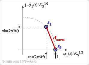
(3) Da der Abstand von einem zum nächstgelegenen Punkt für alle $i$ gleich ist, können wir $d$ beispielsweise aus den Signalraumpunkten $\boldsymbol{s}_0$ und $\boldsymbol{s}_1$ berechnen. Betrachten Sie dabei die nachfolgende Skizze. Nach dem Satz von Pythagoras gilt:
- $$d_{\rm norm}^2 \hspace{-0.01cm}=\hspace{-0.01cm} \sin^2(\frac{2\pi}{M}) + [1- \cos(\frac{2\pi}{M})]^2 $$
- $$\Rightarrow \hspace{0.3cm} d_{\rm norm}^2 \hspace{-0.01cm}=\hspace{-0.01cm} 2 \cdot [1- \cos( \frac{2\pi}{M} )] = 4 \cdot \sin^2(\pi/M )\hspace{0.05cm} $$
- $$\Rightarrow \hspace{0.3cm} d_{\rm norm}= 2 \cdot \sin({\pi}/{M }) \hspace{0.3cm} \Rightarrow \hspace{0.3cm} d = 2\sqrt {E_{\rm S}} \cdot \sin{\pi}/{M })\hspace{0.05cm}.$$
Daraus ergeben sich folgende Zahlenwerte:
- $$M = 8\hspace{-0.09cm}: \hspace{0.2cm}d \hspace{-0.1cm} \ = \ \hspace{-0.1cm} \underline{0.765} \cdot \sqrt {E_{\rm S} } \hspace{0.05cm},$$
- $$M = 16\hspace{-0.09cm}: \hspace{0.2cm} d \hspace{-0.1cm} \ = \ \hspace{-0.1cm} \underline{0.390} \cdot \sqrt {E_{\rm S} } \hspace{0.05cm}.$$
(4) Mit dem Ergebnis aus (3) erhält man mit der vorne angegebenen Gleichung:
- $$p_{\rm S} \le p_{\rm UB} = 2 \cdot {\rm Q} \left [ \sin ({ \pi}/{ M}) \cdot \sqrt{ { 2E_{\rm S}}/{ N_0}} \right ] \hspace{0.05cm}.$$
- Mit $E_{\rm S}/N_0 = 50$ ⇒ $(2E_{\rm S}/N_0)^{\rm 0.5} = 10$ folgt daraus:
- $$M = 8\hspace{-0.09cm}: \hspace{0.2cm}p_{\rm UB} \hspace{-0.1cm} \ = \ \hspace{-0.1cm} 2 \cdot {\rm Q} ( 10 \cdot 0.383 )= 2 \cdot {\rm Q} ( 3.83 ) \approx \underline{0.014 \%} \hspace{0.05cm},$$
- $$ M = 16\hspace{-0.09cm}: \hspace{0.2cm} p_{\rm UB} \hspace{-0.1cm} \ = \ \hspace{-0.1cm} 2 \cdot {\rm Q} ( 10 \cdot 0.195 )= 2 \cdot {\rm Q} ( 1.95 ) \approx \underline{6 \%} \hspace{0.05cm}.$$
- Die Fehlerwahrscheinlichkeit wird also mit steigendem $M$ immer größer, wenn man – wie hier – von konstantem $E_{\rm S}/N_0$ ausgeht.
- Der günstigste Wert ergäbe sich für $M = 2$ (der Faktor $2$ der Union Bound ist dann nämlich nicht notwendig) zu
- $$M = 2\hspace{-0.09cm}: \hspace{0.2cm}p_{\rm UB} = p_{\rm S} = {\rm Q} ( 10 ) \approx { 10^{-23}}.$$
- Mehrstufige PSK würde also keinen Sinn machen, wenn es nicht andere Gründe für deren Anwendung gäbe, worauf in der Teilaufgabe (6) noch eingegangen wird.
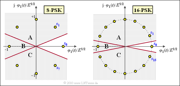
(5) Richtig ist JA. Die Grafik zeigt die Konstellation für 8–PSK und 16–PSK, jeweils gültig unter der Annahme, dass $\boldsymbol{s}_0$ gesendet wurde. Die Höhenlinien der AWGN–WDF sind dann Kreise um $\boldsymbol{s}_0$.
Es gelten folgende Aussagen:
- Die tatsächliche Fehlerwahrscheinlichkeit $p_{\rm S}$ setzt sich aus den Anteilen A, B und C zusammen.
- Dagegen ergibt sich die "Union Bound" aus A + B (Verfälschung in das Symbol $\boldsymbol{s}_1$) plus B + C (Verfälschung in das Symbol $\boldsymbol{s}_{M-1}$).
- Damit gilt stets $p_{\rm S} = p_{\rm UB}$ – B. Der Anteil B ist aber um so kleiner, je größer $M$ ist.
(6) Zur Überprüfung gehen wir beispielsweise von $p_{\rm B} = 10^{\rm –4}$ aus. Daraus folgt für $M = 2$ und $M = 4$:
- $$p_{\rm B} ={\rm Q} \left ( \sqrt{ { {2E_{\rm B}}}/{ N_0} }\right ) = 10^{-4}\hspace{0.3cm}\Rightarrow \hspace{0.3cm} \sqrt{ { {2E_{\rm B}}}/{ N_0} } \approx 3.72 \hspace{0.05cm}.$$
Dagegen gilt mit der angegebenen Gleichung für $M = 8$:
- $$p_{\rm B} \hspace{-0.1cm} \ \le \ \hspace{-0.1cm} \frac{2}{{\rm log_2} \hspace{0.05cm}(M)} \cdot {\rm Q} \left ( \sqrt{{\rm log_2} \hspace{0.05cm}(M)} \cdot \sin ({ \pi}/{ M}) \cdot \sqrt{ { {2E_{\rm S}}}/{ N_0} }\right )= {2}/{3} \cdot {\rm Q} \left ( \sqrt{3} \cdot 0.383 \cdot 3.72 \right ) \approx {2}/{3} \cdot {\rm Q} \left ( 2.46 \right ) \approx 0.46 \% \hspace{0.05cm}.$$
Entsprechend erhält man für $M = 16$ ⇒ ${\rm log}_2 (M) = 4$:
- $$p_{\rm B} = {2}/{4} \cdot {\rm Q} \left ( \sqrt{4} \cdot 0.195 \cdot 3.72 \right ) \approx {1}/{2} \cdot {\rm Q} \left ( 1.45 \right ) \approx 4.8 \% \hspace{0.05cm}.$$
Richtig sind also die Aussagen 1 und 4:
- Der wesentliche Vorteil einer höherstufigen PSK ist also nicht die niedrigere Bitfehlerrate, sondern der geringere Bedarf an der sehr teueren Ressource "Bandbreite".
- Außerdem ist zu beachten, dass die Ergebnisse völlig anders sind, wenn ein (stark) verzerrender Kanal vorliegt, wie in der Leitungsgebundenen Übertragungstechnik üblich.


