Difference between revisions of "Aufgaben:Exercise 1.6: Cyclic Redundancy Check"
| Line 1: | Line 1: | ||
| − | {{quiz-Header|Buchseite= | + | {{quiz-Header|Buchseite=Examples_of_Communication_Systems/ISDN_Primary_Multiplex_Connection |
}} | }} | ||
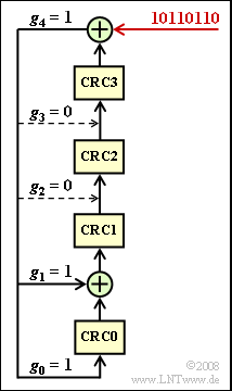
| − | [[File:P_ID1626__Bei_A_1_6.png|right|frame| | + | [[File:P_ID1626__Bei_A_1_6.png|right|frame|Formation of the CRC4 checksum]] |
| − | + | The synchronization happens at the primary multiplex connection in each case in channel $0$ – the synchronization channel - of each frame: | |
| − | * | + | * For odd time frames (number 1, 3, ... , 15) this transmits the so-called "frame password" with the fixed bit pattern $\rm X001\hspace{0.05cm} 1011$. |
| − | * | + | * Each even frame (with number 2, 4, ... , 16) on the other hand contains the "message word" $\rm X1DN\hspace{0.05cm}YYYY$. |
| − | * | + | *Error messages are signaled via the $\rm D$ bit and the $\rm N$ bit, and the four $\rm Y$ bits are reserved for service functions. |
| − | + | The $\rm X$ bit is obtained in each case by the ''CRC4'' method, the implementation of which is shown in the diagram: | |
| − | * | + | *From eight input bits each - in the entire exercise the bit sequence $\rm 1011\hspace{0.05cm} 0110$ is assumed for this purpose - the four check bits $\rm CRC3$, ... , $\rm CRC0$ are obtained by modulo-2 additions and shifts, which are added to the input word in this order. |
| − | * | + | *Before the first bit is shifted into the register, all registers are filled with zeros: |
:$${\rm CRC3 = CRC2 =CRC1 =CRC0 = 0}\hspace{0.05cm}.$$ | :$${\rm CRC3 = CRC2 =CRC1 =CRC0 = 0}\hspace{0.05cm}.$$ | ||
| − | * | + | *After eight shift clocks, the four registers $\rm CRC3$, ... , $\rm CRC0$ contains the CRC4 checksum. |
| Line 38: | Line 38: | ||
''Hinweise:'' | ''Hinweise:'' | ||
| − | *Die Aufgabe gehört zum Kapitel [[Examples_of_Communication_Systems/ | + | *Die Aufgabe gehört zum Kapitel [[Examples_of_Communication_Systems/ISDN_Primary_Multiplex_Connection|"ISDN Primary Multiplex Connection"]] . |
*Zur Lösung der Aufgabe werden einige Grundkenntnisse der [[Channel_Coding|Kanalcodierung]] vorausgesetzt. | *Zur Lösung der Aufgabe werden einige Grundkenntnisse der [[Channel_Coding|Kanalcodierung]] vorausgesetzt. | ||
Revision as of 15:00, 11 October 2022
The synchronization happens at the primary multiplex connection in each case in channel $0$ – the synchronization channel - of each frame:
- For odd time frames (number 1, 3, ... , 15) this transmits the so-called "frame password" with the fixed bit pattern $\rm X001\hspace{0.05cm} 1011$.
- Each even frame (with number 2, 4, ... , 16) on the other hand contains the "message word" $\rm X1DN\hspace{0.05cm}YYYY$.
- Error messages are signaled via the $\rm D$ bit and the $\rm N$ bit, and the four $\rm Y$ bits are reserved for service functions.
The $\rm X$ bit is obtained in each case by the CRC4 method, the implementation of which is shown in the diagram:
- From eight input bits each - in the entire exercise the bit sequence $\rm 1011\hspace{0.05cm} 0110$ is assumed for this purpose - the four check bits $\rm CRC3$, ... , $\rm CRC0$ are obtained by modulo-2 additions and shifts, which are added to the input word in this order.
- Before the first bit is shifted into the register, all registers are filled with zeros:
- $${\rm CRC3 = CRC2 =CRC1 =CRC0 = 0}\hspace{0.05cm}.$$
- After eight shift clocks, the four registers $\rm CRC3$, ... , $\rm CRC0$ contains the CRC4 checksum.
Die Anzapfungen des Schieberegisters sind $g_{0} = 1, \ g_{1} = 1, \ g_{2} = 0, \ g_{3} = 0$ und $g_{4} = 1$.
- Das dazugehörige Generatorpolynom lautet:
- $$G(D) = D^4 + D +1 \hspace{0.05cm}.$$
- Die sendeseitige CRC4–Prüfsumme erhält man auch als Rest der Polynomdivision
- $$(D^{11} +D^{9} +D^{8}+D^{6}+D^{5})/G(D) \hspace{0.05cm}.$$
- Das Divisorpolynom ergibt sich aus der Eingangsfolge und vier angehängten Nullen: $\rm 1011\hspace{0.09cm} 0110\hspace{0.09cm} 0000$.
Auch die CRC4–Überprüfung beim Empfänger entsprechend Teilaufgabe (4) kann durch eine Polynomdivision dargestellt werden. Sie lässt sich durch eine Schieberegisterstruktur in ähnlicher Weise realisieren wie die sendeseitige Gewinnung der CRC4–Prüfsumme.
Hinweise:
- Die Aufgabe gehört zum Kapitel "ISDN Primary Multiplex Connection" .
- Zur Lösung der Aufgabe werden einige Grundkenntnisse der Kanalcodierung vorausgesetzt.
Fragebogen
Musterlösung
(1) Richtig ist der Lösungsvorschlag 2:
- Aufgrund des größten Zählerexponenten $(D^{11})$ und des höchsten Nennerexponenten $(D^{4})$ kann der erste Vorschlag $E(D) = D^{5} + D^{3} + 1$ als Ergebnis ausgeschlossen werden ⇒ $E(D) = D^{7} + D^{5} + D^{3} + 1$.
- Die Modulo–2–Multiplikation von $E(D)$ mit dem Generatorpolynom $G(D) = D^{4} + D + 1$ liefert:
- $$E(D) \cdot G(D) \ = \ (D^7+ D^5+D^3+1)\cdot (D^4+ D+1) \ = D^{11}+D^8+D^7+D^9+D^6+D^5+D^7+D^4+D^3+D^4+ D+1 \hspace{0.05cm}.$$
- Zu berücksichtigen ist hierbei, dass bei Modulo–2–Rechnungen $D^{4} + D^{4} = 0$ gilt. Damit ergibt sich der folgende Rest:
- $$R(D) = D^{11}+D^9+D^8+D^6+D^5- E(D) \cdot G(D) = D^3+D+1 \hspace{0.05cm}.$$
(2) Aus dem Ergebnis der Teilaufgabe (1) folgt:
- $${\rm CRC0 = 1},\hspace{0.2cm}{\rm CRC1 = 1},\hspace{0.2cm}{\rm CRC2 = 0},\hspace{0.2cm}{\rm CRC3 = 1}\hspace{0.05cm}.$$
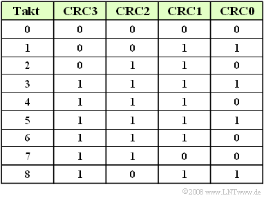
Die Tabelle zeigt einen zweiten Lösungsweg auf: Sie enthält die Registerbelegungen der gegebenen Schaltung zu den Zeiten 0, ... , 8.
(3) Richtig ist nur der Lösungsvorschlag 2.:
- Der Empfänger teilt das Polynom $P(D)$ der Empfangsfolge durch das Generatorpolynom $G(D)$.
- Liefert diese Modulo–2–Division den Rest $R(D) = 0$, so wurden alle 12 Bit richtig übertragen.
- Dies trifft für den zweiten Lösungsvorschlag zu, wie ein Vergleich mit den Teilaufgaben (1) und (2) zeigt. Es gilt ohne Rest:
- $$(D^{11}+D^9+D^8+D^6+D^5+D^3+D+1) : (D^4+ D+1)= D^7+D^5+D^3+1 \hspace{0.05cm}.$$
- Bei Lösungsvorschlag 1 wurde das 6. Informationsbit verfälscht, beim Lösungsvorschlag 3 das CRC1–Bit.
(4) Richtig sind die Lösungsvorschläge 1 und 3:
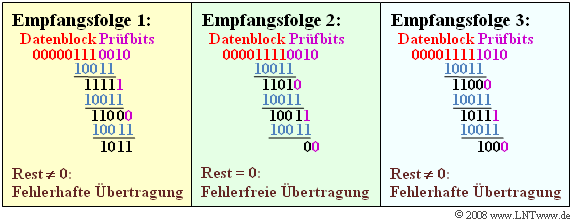
- Die Grafik verdeutlicht die Modulo–2–Divisionen für die gegebenen Empfangsfolgen in vereinfachter Form (mit Nullen und Einsen).
- Man erkennt, dass nur bei der Folge 2 die Division ohne Rest möglich ist.
- In ausgeschriebener Form lauten die Polynomdivisionen:
- $$\ (1) \ \hspace{0.2cm}(D^6+D^5+D^4+1) : (D^4+ D+1)\hspace{0.3cm}\Rightarrow \hspace{0.3cm}{\rm Rest}\hspace{0.15cm}D^3+ D+1\hspace{0.05cm},$$
- $$\ (2) \ \hspace{0.2cm}(D^7+D^6+D^5+D^4+1) : (D^4+ D+1)\hspace{0.3cm}\Rightarrow \hspace{0.3cm}{\rm ohne \hspace{0.15cm}Rest}\hspace{0.05cm},$$
- $$\ (3) \ \hspace{0.2cm}(D^7+D^6+D^5+D^4+D^3+1) : (D^4+ D+1) \hspace{0.3cm}\Rightarrow \hspace{0.3cm}{\rm Rest}\hspace{0.15cm}D^3\hspace{0.05cm}.$$


