Difference between revisions of "Aufgaben:Exercise 1.4Z: Modified MS43 Code"
| Line 39: | Line 39: | ||
|type="[]"} | |type="[]"} | ||
- 4B3T is in principle better than the redundancy-free binary code. | - 4B3T is in principle better than the redundancy-free binary code. | ||
| − | + The transmitted signal should be free of DC | + | + The transmitted signal should be free of DC signals if the channel frequency response $H_{\rm K}(f = 0) = 0$. |
+ A small symbol rate $(1/T)$ allows a longer cable length. | + A small symbol rate $(1/T)$ allows a longer cable length. | ||
| Line 63: | Line 63: | ||
{{ML-Kopf}} | {{ML-Kopf}} | ||
| − | '''(1)''' <u>Statements 2 and 3</u> are correct: | + | '''(1)''' <u>Statements 2 and 3</u> are correct: |
| − | *The first statement is not true: For example, the AWGN channel (additive white Gaussian noise) with a 4B3T code results in a much larger error probability due to the ternary decision compared to the redundancy-free binary code | + | *The first statement is not true: For example, the AWGN channel ("additive white Gaussian noise") with a 4B3T code results in a much larger error probability due to the ternary decision compared to the redundancy-free binary code. |
| − | |||
| − | |||
| − | |||
| + | *The essential reason for the use of a redundant transmission code is rather that no DC signal component can be transmitted via a "telephone channel". | ||
| + | *The $25 \%$ smaller symbol rate $(1/T)$ of the 4B3T code also accommodates the transmission characteristics of copper lines (strong increase in attenuation with frequency). | ||
| − | '''(2)''' With the initial value ${\it \Sigma}_{0} = 0$, the 4B3T coding results in: | + | *For a given line attenuation, therefore, a greater length can be bridged with the 4B3T code than with a redundancy-free binary signal. |
| + | |||
| + | |||
| + | |||
| + | '''(2)''' With the initial value ${\it \Sigma}_{0} = 0$, the 4B3T coding results in: | ||
* '''1100''' ⇒ "+ + +" ⇒ ${\it \Sigma}_{1} = 3$, | * '''1100''' ⇒ "+ + +" ⇒ ${\it \Sigma}_{1} = 3$, | ||
| Line 82: | Line 85: | ||
| − | Thus, the amplitude coefficient we are looking for is $a_{12}\hspace{0.15cm} \underline{ = \ –1}$. | + | Thus, the amplitude coefficient we are looking for is $a_{12}\hspace{0.15cm} \underline{ = \ –1}$. |
[[File:P_ID1341_Dig_A_2_6c.png|right|frame|Markov diagram for the MMS43 code]] | [[File:P_ID1341_Dig_A_2_6c.png|right|frame|Markov diagram for the MMS43 code]] | ||
| − | '''(3)''' From the coloring of the given code table, one can determine the following Markov diagram. | + | '''(3)''' From the coloring of the given code table, one can determine the following Markov diagram. |
| − | *From it, the transition probabilities we are looking for can be read: | + | *From it, the transition probabilities we are looking for can be read: |
:$${\rm Pr}({\it \Sigma}_{l+1} = 0 \ | \ {\it \Sigma}_{l}=0) \ = \ 6/16 \underline{ \ = \ 0.375},$$ | :$${\rm Pr}({\it \Sigma}_{l+1} = 0 \ | \ {\it \Sigma}_{l}=0) \ = \ 6/16 \underline{ \ = \ 0.375},$$ | ||
| Line 96: | Line 99: | ||
| − | '''(4)''' <u>Statements 2 and 3</u> are correct: | + | '''(4)''' <u>Statements 2 and 3</u> are correct: |
*The first statement is false, which can be seen from the asymmetries in the Markov diagram. | *The first statement is false, which can be seen from the asymmetries in the Markov diagram. | ||
*On the other hand, there are symmetries with respect to the states "0" and "3" and between "1" and "2". | *On the other hand, there are symmetries with respect to the states "0" and "3" and between "1" and "2". | ||
Revision as of 11:08, 20 October 2022
For ISDN data transmission, the MMS43 code is used in Germany and Belgium on the so-called "$\rm U_{\rm K0}$" interface $($transmission path between the exchange and the NTBA$)$.
The abbreviation "MMS43" stands for "Modified Monitored Sum 4B3T".
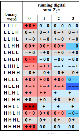
This is a 4B3T block code with the four code tables shown in the graphic, which are used for coding according to the so-called "running digital sum" $($after $l$ blocks$)$:
- $${\it \Sigma}\hspace{0.05cm}_l = \sum_{\nu = 1}^{3 \hspace{0.05cm}\cdot \hspace{0.05cm} l}\hspace{0.02cm} a_\nu$$
For initialization: ${\it \Sigma}_{0} = 0$ is used.
The colorings in the graph mean:
- If the running digital sum does not change $({\it \Sigma}\hspace{0.05cm}_{l+1} = {\it \Sigma}\hspace{0.05cm} _{l})$, a field is grayed out.
- An increase $({\it \Sigma}\hspace{0.05cm}_{l+1} > {\it \Sigma}\hspace{0.05cm}_{l})$ is highlighted in red, a decrease $({\it \Sigma}\hspace{0.05cm}_{l+1} < {\it \Sigma}\hspace{0.05cm} _{l})$ in blue.
- The more intense these colors are, the greater the change in the running digital sum.
Notes:
- The exercise belongs to the chapter "ISDN Basic Access".
- Information about the MMS43 code can be found in the chapter "Block Coding with 4B3T Codes" of the book "Digital signal transmission".
Questions
Solution
(1) Statements 2 and 3 are correct:
- The first statement is not true: For example, the AWGN channel ("additive white Gaussian noise") with a 4B3T code results in a much larger error probability due to the ternary decision compared to the redundancy-free binary code.
- The essential reason for the use of a redundant transmission code is rather that no DC signal component can be transmitted via a "telephone channel".
- The $25 \%$ smaller symbol rate $(1/T)$ of the 4B3T code also accommodates the transmission characteristics of copper lines (strong increase in attenuation with frequency).
- For a given line attenuation, therefore, a greater length can be bridged with the 4B3T code than with a redundancy-free binary signal.
(2) With the initial value ${\it \Sigma}_{0} = 0$, the 4B3T coding results in:
- 1100 ⇒ "+ + +" ⇒ ${\it \Sigma}_{1} = 3$,
- 0100 ⇒ " – + 0" ⇒ ${\it \Sigma}_{2} = 3$,
- 0110 ⇒ "– – +" ⇒ ${\it \Sigma}_{3} = 2$,
- 1010 ⇒ "+ – –" ⇒ ${\it \Sigma}_{4} = 1$.
Thus, the amplitude coefficient we are looking for is $a_{12}\hspace{0.15cm} \underline{ = \ –1}$.
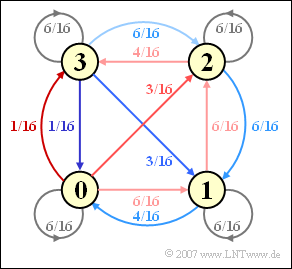
(3) From the coloring of the given code table, one can determine the following Markov diagram.
- From it, the transition probabilities we are looking for can be read:
- $${\rm Pr}({\it \Sigma}_{l+1} = 0 \ | \ {\it \Sigma}_{l}=0) \ = \ 6/16 \underline{ \ = \ 0.375},$$
- $${\rm Pr}({\it \Sigma}_{l+1} = 2 \ | \ {\it \Sigma}_{l}=0) \ = \ 3/16 \underline{ \ = \ 0.1875},$$
- $${\rm Pr}({\it \Sigma}_{l+1} = 0 \ | \ {\it \Sigma}_{l}=2) \underline{ \ = \ 0}.$$
(4) Statements 2 and 3 are correct:
- The first statement is false, which can be seen from the asymmetries in the Markov diagram.
- On the other hand, there are symmetries with respect to the states "0" and "3" and between "1" and "2".
In the following calculation, instead of ${\rm Pr}({\it \Sigma}_{l} = 0)$, we write ${\rm Pr}(0)$ in a simplified way. Taking advantage of the property ${\rm Pr}(3) = {\rm Pr}(0)$ and ${\rm Pr}(2) = {\rm Pr}(1)$, we get the following equations from the Markov diagram:
- $${\rm Pr}(0)= \frac{6}{16} \cdot {\rm Pr}(0) + \frac{4}{16} \cdot {\rm Pr}(1)+ \frac{1}{16} \cdot {\rm Pr}(3)\hspace{0.3cm} \Rightarrow \hspace{0.3cm}\frac{9}{16} \cdot {\rm Pr}(0)= \frac{4}{16} \cdot {\rm Pr}(1).$$
From the further condition ${\rm Pr}(0) + {\rm Pr}(1) = 1/2$ t follows further:
- $${\rm Pr}(0)= {\rm Pr}(3)= \frac{9}{26}\hspace{0.05cm}, \hspace{0.2cm} {\rm Pr}(1)= {\rm Pr}(2)= \frac{4}{26}\hspace{0.05cm}.$$
This calculation is based on the sum of the incoming arrows in the "0" condition.
One could also give equations for the other three states, but they all give the same result:
- $${\rm Pr}(1) \ = \ \frac{6}{16} \cdot {\rm Pr}(0) + \frac{6}{16} \cdot {\rm Pr}(1)+ \frac{6}{16} \cdot {\rm Pr}(2)+\frac{3}{16} \cdot {\rm Pr}(3)\hspace{0.05cm},$$
- $$ {\rm Pr}(2) \ = \ \frac{3}{16} \cdot {\rm Pr}(0) + \frac{6}{16} \cdot {\rm Pr}(1)+ \frac{6}{16} \cdot {\rm Pr}(2)+\frac{6}{16} \cdot {\rm Pr}(3)\hspace{0.05cm},$$
- $$ {\rm Pr}(3) \ = \ \frac{1}{16} \cdot {\rm Pr}(0) + \frac{4}{16} \cdot {\rm Pr}(2)+\frac{6}{16} \cdot {\rm Pr}(3)\hspace{0.05cm}.$$

