Exercise 2.7: Two-Way Channel once more
As in Exercise 2.6, a two-way channel is considered whose impulse response is:
- $$h(t) = \delta ( t - T_1) + \delta ( t - T_2).$$
In contrast to the general representation in exercise 2.6, the two attenuation factors are equal here: $z_1 = z_2 = 1$.
- For mobile communications, this corresponds to an echo at a distance of $T_2 - T_1$ and of the same strength as the signal on the main path, for example.
- For this, the transit time $T_1$ is assumed.
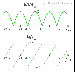
Using the transit times $T_1 = 0$ and $T_2 = T = 4 \ \rm ms$ considered in the subtasks (1) ... (4), the following is obtained for the frequency response of the two-way channel, whose magnitude is depicted in the upper graph:
- $$H(f) = 1 + {\rm e}^{-{\rm j}\hspace{0.04cm}2 \pi f T} = 1 + \cos(2 \pi f T) - {\rm j} \cdot \sin(2 \pi f T)$$
- $$\Rightarrow \hspace{0.4cm}|H(f)| = \sqrt{2\left(1 + \cos(2 \pi f T)\right)}= 2 \cdot |\cos(\pi f T)|.$$
The bottom graph shows the phase function:
- $$b(f) = - {\rm arc} \hspace{0.1cm}H(f) = \arctan \frac{\sin(2 \pi f T)}{1 + \cos(2 \pi f T)} = \arctan \big[\tan(\pi f T)\big].$$
The following trigonometric transformation was used here:
- $$ \frac{\sin(2 \alpha)}{1 + \cos(2 \alpha)} = \tan(\alpha).$$
The bottom graph shows the phase function for $T_1 = 0$ and $T_2 = T = 4 \ \rm ms$:
- In the frequency range $|f| < 1/(2T)$, $b(f)$ increases linearly: $b(f) = \pi \cdot f \cdot T.$
- Also in further sections of the phase function, the phase always increases linearly from $-\pi/2$ to $+\pi/2$ .
In the questions, $y_i(t)$ denotes the signal at the output of the two-way channel if the signal $x_i(t)$ is applied to the input $( i = 1, 2, 3, 4)$.
These signals are examined as input signals:
- a rectangular pulse $x_1(t)$ with height $1$ between $t= 0$ and $t= T$;
$x_1(t) = 0$ holds for $t < 0$ and $t > T$ $($the value $0.5$ occurs at the two jump discontinuities, respectively$)$; - a rectangular pulse $x_2(t)$ with height $1$ in the range of $0 \ \text{...} \ 2T$;
- a periodic rectangular pulse $x_3(t)$ with period $T = T_0$:
- $$x_3(t) = \left\{ \begin{array}{c} 1 \\ 0 \\ \end{array} \right.\quad \quad \begin{array}{c} {\rm{for}} \\ {\rm{for}} \\ \end{array}\begin{array}{*{20}c} { 0 < t < T/2,} \\ { T/2 < t < T,} \\ \end{array}$$
- a periodic rectangular pulse $x_4(t)$ with period $T = 2T_0$:
- $$x_4(t) = \left\{ \begin{array}{c} 1 \\ 0 \\ \end{array} \right.\quad \quad \begin{array}{c} {\rm{for}} \\ {\rm{for}} \\ \end{array}\begin{array}{*{20}c} { 0 < t < T,} \\ { T < t < 2T.} \\ \end{array}$$
Please note:
- The task belongs to the chapter Linear Distortions.
- For subtasks (1) to (4), $T_1 = 0$ and $T_2 = T = 4 \ \rm ms$ hold.
- In subtask (5), the case $T_1 = 1 \ \rm ms$ and $T_2 = 5 \ \rm ms$ is considered.
Questions
Solution
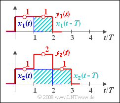
- $$y_1(t) = x_1(t) \star h(t) = x_1(t) \star \delta (t) + x_1(t) \star \delta (t - T) = x_1(t) + x_1(t-T).$$
- Thus, $y_1(t)$ is a rectangular pulse of height $1$ and width $2T$.
- The same result – but in a more time-consuming way – is obtained by computing in the spectral domain:
- $$Y_1(f) = X_1(f) \cdot H(f) = T \cdot \frac {\sin(\pi f T)}{\pi f T}\cdot {\rm e}^{-{\rm j}\hspace{0.05cm} \cdot \hspace{0.05cm} \pi f T} \cdot \big[ 1 + {\rm e}^{-{\rm j}\hspace{0.05cm} \cdot \hspace{0.05cm}2 \pi f T} \big].$$
- The complex exponential functions can be converted using the Euler theorem as follows:
- $${\rm e}^{-{\rm j}\hspace{0.05cm} \cdot \hspace{0.05cm} \pi f T} \big[ 1 + {\rm e}^{-{\rm j}\hspace{0.05cm} \cdot \hspace{0.05cm}2 \pi f T} \big] = {\rm e}^{-{\rm j}\hspace{0.05cm} \cdot \hspace{0.05cm}2 \pi f T} \cdot \big[ {\rm e}^{{\rm j}\hspace{0.05cm} \cdot \hspace{0.05cm} \pi f T} + {\rm e}^{-{\rm j}\hspace{0.05cm} \cdot \hspace{0.05cm} \pi f T} \big] = {\rm e}^{-{\rm j}\hspace{0.05cm} \cdot \hspace{0.05cm}2 \pi f T} \cdot 2 \cos(\pi f T) .$$
- Hence, the following can be formulated for the output spectrum:
- $$Y_1(f) = Y_{11}(f) \cdot {\rm e}^{-{\rm j}\hspace{0.05cm} \cdot \hspace{0.05cm}2 \pi f T} , \; \; {\rm mit } \; \; Y_{11}(f) = 2T \cdot \frac {\sin(\pi f T) \cdot \cos(\pi f T)}{\pi f T} = 2T \cdot \frac {\sin(2\pi f T) }{2\pi f T}.$$
Here, the relation $\sin(\alpha) \cdot \cos(\alpha) = \sin(2\alpha)/2$ is used.
- The inverse Fourier transform of $Y_{11}$ results in a rectangle of width $2T$, that is symmetric about $t = 0$ .
- Due to the phase function this is shifted into the range $0$ ... $2T$ and the result of the time domain computation is confirmed.
Despite the fact that $y_1(t)$ is rectangular just as $x_1(t)$, there are distortions:
- These are linear because of $T_y > T_x$ . In the frequency range of interest $($that is all frequencies for a si–shaped spectrum$)$, $|H(f)|$ is not constant. So, there are attenuation distortions.
- In addition, there are also phase distortions since the phase does not increase linearly with $f$ in the whole range ⇒ The proposed solutions 1, 3, 4 and 5 are correct.
(2) Due to the equation
- $$y_2(t) = x_2(t) + x_2(t-T)$$
already specified in (1) a step-like curve shape corresponding to the lower diagram of the upper graph is obtained.
The numerical values that are looked for are: $y_2(t = 0.5 T) \hspace{0.15cm}\underline{= 1}, \hspace{0.3cm} y_2(t = 1.5 T) \hspace{0.15cm}\underline{= 2}, \hspace{0.3cm}y_2(t = 2.5 T) \hspace{0.15cm}\underline{ = 1}.$
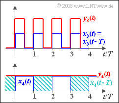
(3) The period $T_0 = T$ of the periodic signal $x_3(t)$ is exactly as large as the delay on the second path. Therefore, $y_3(t) = 2 \cdot x_3(t) $ holds and no distortions are observable.
The spectral domain computation leads to the same result.
- $X_3(f)$ is a line spectrum with components at frequencies $f = 0$, $f = \pm f_0 = \pm 1/T$, $f = \pm 3f_0$, etc..
- However, the following holds at these discrete frequencies:
- $$|H(f)| = 2, \hspace{0.3cm} b(f) = 0 \hspace{0.3cm} \Rightarrow \hspace{0.3cm}\tau_{\rm P}(f) = 0.$$
- From this it follows again that $y_3(t) = 2 \cdot x_3(t) $.
- Thus, only proposed solution 1 is correct.
(4) It can be seen that $y_4(t) = 1$ is distorted with respect to $x_4(t)$ from the lower sketch of the second graph. These are attenuation distortions ⇒ Proposed solution 2 is correct as the following consideration shows.
- Due to $T_0 = 2T$ the signal $x_4(t)$ has the fundamental frequency $f_0 = 1/(2T)$.
- The frequency response thus has zeros for all odd multiples of $f_0$ .
- The only remaining spectral line of $Y_4(f)$ is at $f = 0$ where the following holds:
- $$Y_4(f) = 2 \cdot 0.5 \cdot \delta (f) = 1 \cdot \delta (f) \hspace{0.5cm}\Rightarrow \hspace{0.5cm} y_4(t) = 1.$$
(5) Now the frequency response is with $T_1 = 1 \ \rm ms$, $T_2 = 5 \ \rm ms$ and $T = T_2 -T_1 = 4 \ \rm ms$:
- $$H(f) = {\rm e}^{-{\rm j}\hspace{0.05cm} \cdot \hspace{0.05cm}2 \pi f T_1}+ {\rm e}^{-{\rm j}\hspace{0.05cm} \cdot \hspace{0.05cm}2 \pi f T_2}= \big[ 1 + {\rm e}^{-{\rm j}\hspace{0.05cm} \cdot \hspace{0.05cm}2 \pi f T} \big]\cdot {\rm e}^{-{\rm j}\hspace{0.05cm} \cdot \hspace{0.05cm}2 \pi f T_1}.$$
- The expression in parentheses describes the frequency response already considered so far.
- The second term causes an additional runtime around $ \tau = T_1$ and the following holds for all signals $(i = 1, 2, 3, 4)$:
- $$y_i^{\rm (5)}(t) = y_i(t-T_1).$$
All statements regarding the distortions are still valid. This corresponds to proposed solution 1.


