Contents
Applet Description
The applet is intended to illustrate the „Doppler effect”, named after the Austrian mathematician, physicist and astronomer Christian Andreas Doppler. This predicts the change in the perceived frequency of waves of any kind, which occurs when the source (transmitter) and observer (receiver) move relative to each other. Because of this, the reception frequency $f_{\rm E}$ differs from the transmission frequency $f_{\rm S}$. The Doppler frequency $f_{\rm D}=f_{\rm E}-f_{\rm S}$ is positive if the observer and the source approach each other, otherwise the observer perceives a lower frequency than which was actually transmitted.
The exact equation for the reception frequency $f_{\rm E}$ considering the theory of relativity is:
- $$f_{\rm E} = f_{\rm S} \cdot \frac{\sqrt{1 - (v/c)^2} }{1 - v/c \cdot \cos(\alpha)}\hspace{0.3cm} \Rightarrow \hspace{0.3cm} {\text{ exact equation}}.$$
- Here is $v$ the relative speed between transmitter and receiver, while $c = 3 \cdot 10^8 \, {\rm m/s}$ indicates the speed of light.
- $\alpha$ is the angle between the direction of movement and the connecting line between transmitter and receiver.
- $\varphi$ denotes the angle between the direction of movement and the horizontal in the applet. In general, $\alpha \ne \varphi$.
At realistic speeds $(v/c \ll 1)$ the following approximation is sufficient, ignoring the effects of relativity:
- $$f_{\rm E} \approx f_{\rm S} \cdot \big [1 +{v}/{c} \cdot \cos(\alpha) \big ] \hspace{0.3cm} \Rightarrow \hspace{0.3cm}{\text{ approximation}}\hspace{0.05cm}.$$
For example, in the case of mobile communications, the deviations between $f_{\rm E}$ and $f_{\rm S}$ – the Doppler frequency $f_{\rm D}$ – only a fraction of the transmission frequency.
Theoretical Background
Phenomenological description of the Doppler effect
$\text{Definition:}$ As $\rm Doppler effect$ is the change in the perceived frequency of waves of any kind that occurs when the source (transmitter) and observer (receiver) move relative to each other. This was invented by the Austrian mathematician, physicist and astronomer Christian Andreas Doppler in the middle of the 19th century theoretically predicted and named after him.
The Doppler impact can be described qualitatively as follows:
- If the observer and the source approach each other, the frequency increases from the observer's point of view, regardless of whether the observer is moving or the source or both.
- If the source moves away from the observer or the observer moves away from the source, the observer perceives a lower frequency than was actually transmitted.
$\text{Beispiel 1:}$ We look at the change in pitch of the "Martinhorn" of an ambulance. As long as the vehicle is approaching, the observer hears a higher tone than when the vehicle is stationary. If the ambulance moves away, a lower tone is perceived.
The same effect can be seen in a car race. The faster the cars drive, the clearer the frequency changes and the “sound”.
$\text{Beispiel 2:}$
Some properties of this effect, which is still known from physics lessons, are now to be shown on the basis of screen shots from an earlier version of the present applet, with the dynamic program properties of course being lost.
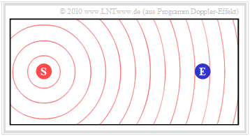
The first graphic shows the initial situation:
- The stationary transmitter $\rm (S)$ emits the constant frequency $f_{\rm S}$.
- The wave propagation is illustrated in the graphic by concentric circles around $\rm (S)$ illustrated.
- The receiver $\rm (E)$ , which is also at rest, receives the frequency $f_{\rm E} = f_{\rm S}$.
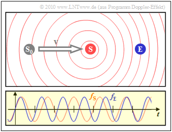
$\text{Beispiel 3:}$ In this snapshot, the transmitter $\rm (S)$ has moved from its starting point $\rm (S_0)$ to the receiver $\rm (E)$ at a constant speed.
- The diagram on the right shows that the frequency $f_{\rm E}$ perceived by the receiver (blue oscillation) is about $20\%$ greater than the frequency $f_{\rm S}$ on the transmitter (red oscillation).
- Due to the movement of the transmitter, the circles are no longer concentric.
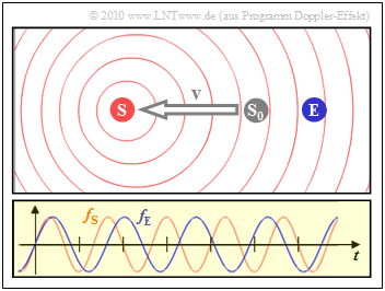
- The left scenario is the result when the sender $\rm (S)$ moves away from the receiver $\rm (E)$:
- Then the reception frequency $f_{\rm E}$(blue oscillation) is about $20\%$ lower than the transmission frequency $f_{\rm S}$.
Doppler frequency as a function of speed and angle of the connecting line
We agree: the frequency $f_{\rm S}$ is sent and the frequency $f_{\rm E}$ is received. The Doppler frequency is the difference $f_{\rm D} = f_{\rm E} - f_{\rm S}$ due to the relative movement between the transmitter (source) and receiver (observer).
- A positive Doppler frequency $(f_{\rm E} > f_{\rm S})$ arises when the transmitter and receiver move (relatively) towards each other.
- A negative Doppler frequency $(f_{\rm E} < f_{\rm S})$ means that the sender and receiver are moving apart (directly or at an angle).
The exact equation for the reception frequency $f_{\rm E}$ including an angle $\alpha$ between the direction of movement and the connecting line between transmitter and receiver is:
- \[f_{\rm E} = f_{\rm S} \cdot \frac{\sqrt{1 - (v/c)^2} }{1 - v/c \cdot \cos(\alpha)}\hspace{0.3cm} \Rightarrow \hspace{0.3cm} {\text{ exact equation}}.\]
Here $v$ denotes the relative speed between transmitter and receiver, while $c = 3 \cdot 10^8 \, {\rm m/s}$ indicates the speed of light.
- The graphics in $\text{Beispiel 3}$ apply to the unrealistically high speed $v = c/5 = 60000\, {\rm km/s}$, which lead to the Doppler frequencies $f_{\rm D} = \pm 0.2\cdot f_{\rm S}$.
- In the case of mobile communications, the deviations between $f_{\rm S}$ and $f_{\rm E}$ are usually only a fraction of the transmission frequency. At such realistic velocities $(v \ll c)$ one can start from the following approximation, which does not take into account the effects described by the theory of relativity:
- \[f_{\rm E} \approx f_{\rm S} \cdot \big [1 +{v}/{c} \cdot \cos(\alpha) \big ] \hspace{0.3cm} \Rightarrow \hspace{0.3cm}{\text{ Näherung}}\hspace{0.05cm}.\]
$\text{Beispiel 4:}$ We are assuming a fixed station here. The receiver approaches the transmitter at an angle $\alpha = 0$.
Different speeds are to be examined:
- an unrealistically high speed $v_1 = 0.6 \cdot c = 1.8 \cdot 10^8 \ {\rm m/s}$ $\hspace{0.3cm}\Rightarrow\hspace{0.3cm}v_1/c = 0.6$,
- the maximum speed $v_2 = 3 \ {\rm km/s} \ \ (10800 \ {\rm km/h})$ for an unmanned test flight $\hspace{0.3cm}\Rightarrow\hspace{0.3cm}v_2/c = 10^{-5}$,
- approx. the top speed $v_3 = 30 \ {\rm m/s} = 108 \ \rm km/h$ on federal roads $\hspace{0.3cm}\Rightarrow\hspace{0.3cm}v_3/c = 10^{-7}$.
(1) According to the exact, relativistic first equation:
- $$f_{\rm E} = f_{\rm S} \cdot \frac{\sqrt{1 - (v/c)^2} }{1 - v/c } \hspace{0.3cm} \Rightarrow \hspace{0.3cm} f_{\rm D} = f_{\rm E} - f_{\rm S} = f_{\rm S} \cdot \left [ \frac{\sqrt{1 - (v/c)^2} }{1 - v/c } - 1 \right ]$$
- $$\hspace{4.8cm} \Rightarrow \hspace{0.3cm}{f_{\rm D} }/{f_{\rm S} } = \frac{\sqrt{1 - (v/c)^2} }{1 - v/c } - 1 \hspace{0.05cm}.$$
- $$\Rightarrow\hspace{0.3cm}v_1/c = 0.6\text{:}\hspace{0.5cm}{f_{\rm D} }/{f_{\rm S} } = \frac{\sqrt{1 - 0.6^2} }{1 - 0.6 } - 1 = \frac{0.8}{0.4 } - 1 \hspace{0.15cm} \underline{ = 1}$$
- $$ \hspace{2.6cm}\Rightarrow\hspace{0.3cm} {f_{\rm E} }/{f_{\rm S} } = 2 \hspace{0.05cm}.$$
- $$\Rightarrow\hspace{0.3cm}v_2/c = 10^{\rm -5}\text{:}\hspace{0.5cm}{f_{\rm D} }/{f_{\rm S} } = \frac{\sqrt{1 - (10^{-5})^2} }{1 - (10^{-5}) } - 1 \approx 1 + 10^{-5} - 1 \hspace{0.15cm} \underline{ = 10^{-5} }$$
- $$\hspace{2.85cm}\Rightarrow\hspace{0.3cm} {f_{\rm E} }/{f_{\rm S} } = 1.00001 \hspace{0.05cm}.$$
- $$\Rightarrow\hspace{0.3cm}v_3/c = 10^{\rm -7}\text{:}\hspace{0.5cm}{f_{\rm D} }/{f_{\rm S} } = \frac{\sqrt{1 - (10^{-7})^2} }{1 - (10^{-7}) } - 1 \approx 1 + 10^{-7} - 1 \hspace{0.15cm} \underline{ = 10^{-7} }$$
- $$\hspace{2.85cm}\Rightarrow\hspace{0.3cm} {f_{\rm E} }/{f_{\rm S} } = 1.0000001 \hspace{0.05cm}.$$
(2) On the other hand, according to the approximation, i.e. without taking into account the theory of relativity:
- $$f_{\rm E} = f_{\rm S} \cdot \big [ 1 + {v}/{c} \big ] \Rightarrow \hspace{0.3cm}{f_{\rm D} }/{f_{\rm S} } = {v}/{c} \hspace{0.05cm}.$$
- $$\Rightarrow\hspace{0.3cm}v_1/c = 0.6\text{:}\hspace{0.7cm} f_{\rm D}/f_{\rm S} \ \ = \ 0.6 \hspace{0.5cm} ⇒ \ \ \ f_{\rm E}/f_{\rm S} = 1.6,$$
- $$\Rightarrow\hspace{0.3cm}v_2/c = 10^{-5}\text{:}\hspace{0.4cm} f_{\rm D}/f_{\rm S} \ = \ 10^{-5} \ \ \ ⇒ \ \ \ f_{\rm E}/f_{\rm S} = 1.00001,$$
- $$\Rightarrow\hspace{0.3cm}v_3/c = 10^{-7}\text{:}\hspace{0.4cm} f_{\rm D}/f_{\rm S} \ = \ 10^{-5} \ \ \ ⇒ \ \ \ f_{\rm E}/f_{\rm S} = 1.0000001.$$
$\text{Conclusion:}$
- For "low" speeds, the approximation to the accuracy of a calculator gives the same result as the relativistic equation.
- The numerical values show that we can also rate the speed $v_2 = \ 10800 \ {\rm km/h}$ as "low" in this respect.
$\text{Beispiel 5:}$ The same requirements apply as in the last example with the difference: Now the receiver moves away from the transmitter $(\alpha = 180^\circ)$.
(1) According to the exact, relativistic first equation with ${\rm cos}(\alpha) = -1$:
- $$f_{\rm E} = f_{\rm S} \cdot \frac{\sqrt{1 - (v/c)^2} }{1 + v/c } \hspace{0.3cm} \Rightarrow \hspace{0.3cm} f_{\rm D} = f_{\rm E} - f_{\rm S} = f_{\rm S} \cdot \left [ \frac{\sqrt{1 - (v/c)^2} }{1 + v/c } - 1 \right ]\hspace{0.3cm}$$
- $$\hspace{4.8cm} \Rightarrow \hspace{0.3cm}{f_{\rm D} }/{f_{\rm S} } = \frac{\sqrt{1 - (v/c)^2} }{1 + v/c } - 1 \hspace{0.05cm}.$$
- $$\Rightarrow\hspace{0.3cm}v_1/c = 0.6\text{:}\hspace{0.5cm}{f_{\rm D} }/{f_{\rm S} } = \frac{\sqrt{1 - 0.6^2} }{1 + 0.6 } - 1 = \frac{0.8}{1.6 } - 1 =-0.5 \hspace{0.3cm}\Rightarrow\hspace{0.3cm} {f_{\rm E} }/{f_{\rm S} } = 0.5 \hspace{0.05cm}.$$
- $$\Rightarrow\hspace{0.3cm}v_2/c = 10^{\rm -5}\text{:}\hspace{0.5cm}{f_{\rm D} }/{f_{\rm S} } = \frac{\sqrt{1 - (10^{-5})^2} }{1 + (10^{-5}) } - 1 \approx - 10^{-5} \hspace{0.3cm}\Rightarrow\hspace{0.3cm} {f_{\rm E} }/{f_{\rm S} } = 0.99999 \hspace{0.05cm}.$$
(2) On the other hand, according to the approximation, i.e. without taking into account the theory of relativity:
- $$f_{\rm E} = f_{\rm S} \cdot \big [ 1 - {v}/{c} \big ] \Rightarrow \hspace{0.3cm}{f_{\rm D} }/{f_{\rm S} } = - {v}/{c} \hspace{0.05cm}.$$
- $$\Rightarrow\hspace{0.3cm}v_1/c = 0.6\text{:}\hspace{0.7cm} f_{\rm D}/f_{\rm S} \ \underline {= \ 0.6} \ \ \ ⇒ \ \ \ f_{\rm E}/f_{\rm S} = 0.4,$$
- $$\Rightarrow\hspace{0.3cm}v_2/c = 10^{-5}\text{:}\hspace{0.4cm} f_{\rm D}/f_{\rm S} \ = \ - 10^{-5} \ \ \ ⇒ \ \ \ f_{\rm E}/f_{\rm S} = 0.99999.$$
$\text{Conclusion:}$
- The reception frequency $f_{\rm E}$ is now lower than the transmission frequency $f_{\rm S}$ and the Doppler frequency $f_{\rm D}$ is negative.
- Using approximation, the Doppler frequencies for the two directions of movement differ only in the sign ⇒ $f_{\rm E} = f_{\rm S} \pm f_{\rm D}$.
- This symmetry does not exist with the exact, relativistic equation.
$\text{Beispiel 6:}$ Now let's look at the speed that is also realistic for mobile communications $v = 30 \ {\rm m/s} = 108 \ \rm km/h$ ⇒ $v/c=10^{-7}$.
- This allows us to limit ourselves to the non-relativistic approximation: $f_{\rm D} = f_{\rm E} - f_{\rm S} = f_{\rm S} \cdot {v}/{c} \cdot \cos(\alpha) \hspace{0.05cm}.$
- As in the previous examples, the transmitter is fixed. The transmission frequency is $f_{\rm S} = 2 \ {\rm GHz}$.
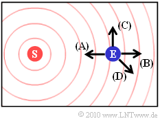
The graphic shows possible directions of movement of the receiver.
- The direction $\rm (A)$ was used in $\text{Beispiel 4}$ . With the current parameter values
- $$f_{\rm D} = 2 \cdot 10^{9}\,\,{\rm Hz} \cdot \frac{30\,\,{\rm m/s} }{3 \cdot 10^{8}\,\,{\rm m/s} } = 200\,{\rm Hz}.$$
- For the direction $\rm (B)$ you get the same numerical value with negative sign according to $\text{Beispiel 5}$:
- $$f_{\rm D} = -200\,{\rm Hz}.$$
- The direction of travel $\rm (C)$ is perpendicular $(\alpha = 90^\circ)$ to the connecting line between transmitter and receiver. In this case there is no Doppler shift:
- $$f_{\rm D} = 0.$$
- The direction of movement $\rm (D)$ is characterized by $\alpha = \ -135^\circ$. This results:
- $$f_{\rm D} = 200 \,{\rm Hz} \cdot \cos(-135^{\circ}) \approx -141\,\,{\rm Hz} \hspace{0.05cm}.$$
Doppler frequency and its distribution
We briefly summarize the statements on the last page, while we proceed with the second, the non – relativistic equation:
- A relative movement between transmitter (source) and receiver (observer) results in a shift by the Doppler frequency $f_{\rm D} = f_{\rm E} - f_{\rm S}$.
- A positive Doppler frequency $(f_{\rm E} > f_{\rm S})$ results when the transmitter and receiver move (relatively) towards each other. A negative Doppler frequency $(f_{\rm E} < f_{\rm S})$ means, that the sender and receiver are moving apart (directly or at an angle).
- The maximum frequency shift occurs when the transmitter and receiver move directly towards each other ⇒ angle $\alpha = 0^\circ$. This maximum value depends in the first approximation on the transmission frequency $ f_{\rm S}$ and the speed $v$ ab $(c = 3 \cdot 10^8 \, {\rm m/s}$ indicates the speed of light$)$: $f_{\rm D, \hspace{0.05cm} max} = f_{\rm S} \cdot {v}/{c} \hspace{0.05cm}.$
- If the relative movement occurs at any angle $\alpha$ to the sender-receiver connecting line, a Doppler shift occurs to the transmitter-receiver connection line, a Doppler shift occurs
- \[f_{\rm D} = f_{\rm E} - f_{\rm S} = f_{\rm D, \hspace{0.05cm} max} \cdot \cos(\alpha) \hspace{0.3cm} \Rightarrow \hspace{0.3cm} - \hspace{-0.05cm}f_{\rm D, \hspace{0.05cm} max} \le f_{\rm D} \le + \hspace{-0.05cm}f_{\rm D, \hspace{0.05cm} max} \hspace{0.05cm}.\]
$\text{Conclusion:}$ Assuming equally probable directions of movement $($Uniform distribution for the angle $\alpha$ in the area $- \pi \le \alpha \le +\pi)$ results for the probability density function $($referred to here as "wdf"$)$ the Doppler frequency in the range $- f_\text{D, max} \le f_{\rm D} \le + f_\text{D, max}$:
- \[{\rm wdf}(f_{\rm D}) = \frac{1}{2\pi \cdot f_{\rm D, \hspace{0.05cm} max} \cdot \sqrt {1 - (f_{\rm D}/f_{\rm D, \hspace{0.05cm} max})^2 } } \hspace{0.05cm}.\]
Outside the range between $-f_{\rm D}$ and $+f_{\rm D}$ , the probability density function is always zero.
$\text{Derivation}$ about the “nonlinear transformation of random quantities”
Power density spectrum in Rayleigh fading
We now presuppose an antenna radiating equally in all directions. Then the Doppler - $ \ rm LDS $ (power density spectrum) has the same shape as the $ \rm WDF $ (probability density function) of the Doppler frequencies.
- For the in-phase component ${\it \Phi}_x(f_{\rm D})$ of the LDS, the WDF must still be multiplied by the power $\sigma^2$ of the Gaussian process.
- For the resulting LDS ${\it \Phi}_z(f_{\rm D})$ of the complex factor $z(t) = x(t) + {\rm j} \cdot y(t) $ applies after doubling:
- \[{\it \Phi}_z(f_{\rm D}) = \left\{ \begin{array}{c} (2\sigma^2)/( \pi \cdot f_{\rm D, \hspace{0.05cm} max}) \cdot \left [ 1 - (f_{\rm D}/f_{\rm D, \hspace{0.05cm} max})^2 \right ]^{-0.5} \\ 0 \end{array} \right.\quad \begin{array}{*{1}c} {\rm f\ddot{u}r}\hspace{0.15cm} |f_{\rm D}| \le f_{\rm D, \hspace{0.05cm} max} \\ {\rm sonst} \\ \end{array} \hspace{0.05cm}.\]
This course is called Jakes spectrum named after William C. Jakes Jr.. The doubling is necessary, because so far only the contribution of the real part $x(t)$has been considered.
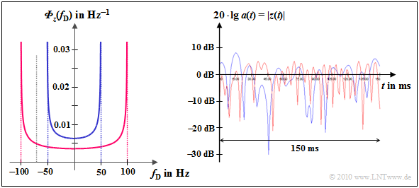
$\text{Example 7:}$ The Jakes spectrum is shown on the left
- for $f_{\rm D, \hspace{0.05cm} max} = 50 \ \rm Hz$ (blue curve) bzw.
- for $f_{\rm D, \hspace{0.05cm} max} = 100 \ \rm Hz$ (red curve).
Beim GSM-D network $(f_{\rm S} = 900 \ \rm MHz)$ these values correspond to the speeds $v = 60 \ \rm km/h$ bzw. $v = 120 \ \rm km/h$.
For the electric network $(f_{\rm S} = 1.8 \ \rm GHz)$ these values apply to speeds that are half as high: $v = 30 \ \rm km/h$ bzw. $v = 60 \ \rm km/h$.
The right picture shows the logarithmic amount of $z(t)$:
- You can see that the red curve is fading twice as fast.
- The Rayleigh – WDF (amplitude distribution) is independent of $f_{\rm D, \hspace{0.05cm} max}$ and is therefore the same for both cases.
Exercises
- First select the number 1 ... 9 of the task to be processed.
- A task description is displayed. The parameter values are adjusted.
- Solution after pressing “sample solution”.
- The number 0 corresponds to a "reset": Same setting as when the program was started.
- In the following descriptions, $f_{\rm S}$, $f_{\rm E}$ and$f_{\rm D}$ are each standardized to the reference frequency $f_{\rm 0}$ normiert.
(1) First we consider the relativistic attitude "Exact". The transmitter moves with $v/c = 0.8$, the transmission frequency is $f_{\rm S}= 1$.
Which reception frequencies $f_{\rm E}$ result in both directions of movement? What is the Doppler frequency $f_{\rm D}$?
- If the transmitter approaches the receiver under the angle $\varphi=0^\circ$ , the reception frequency is $f_{\rm E}= 3$ ⇒ $f_{\rm D}= f_{\rm E} - f_{\rm S}= 2$.
- If the sender moves away from the receiver $($für $\varphi=0^\circ$, if it overtakes it, or $\varphi=180^\circ)$, then: $f_{\rm E}= 0.333$ ⇒ $f_{\rm D}= -0.667$.
- The same result with the transmitter at rest and the receiver moving: If both come closer, then $f_{\rm D}= 2$ applies, otherwise $f_{\rm D}= -0.667$.
(2) The settings are largely retained. How do the results change compared to (1) with the transmission frequency $f_{\rm S}= 1.5$?
Tip for a time-saving experiment: Switch alternately between "right" and "left".
- Direction of movement $\varphi=0^\circ$: $f_{\rm E}= 4.5$ ⇒ $f_{\rm D}= f_{\rm E} - f_{\rm S}= 3$. Thus: $f_{\rm E}/f_{\rm S}= 3$, $f_{\rm D}/f_{\rm S}= 2$ ⇒ Both as in (1).
- Direction of movement $\varphi=180^\circ$: $f_{\rm E}= 0.5$ ⇒ $f_{\rm D}= -1$. Thus: $f_{\rm E}/f_{\rm S}= 0.333$, $f_{\rm D}/f_{\rm S}= -0.667$ ⇒ Both as in (1).
(3) Still relativistic attitude "Exact". The transmitter is now moving at a speed of $v/c = 0.4$ and the transmission frequency is $f_{\rm S}= 2$.
Which frequencies $f_{\rm D}$ and $f_{\rm E}$ result in both directions of movement? Alternately select "Right" or "Left" again.
- Direction of movement $\varphi=0^\circ$: Receive frequency $f_{\rm E}= 3.055$ ⇒ Doppler frequency $f_{\rm D}= 1.055$. ⇒ $f_{\rm E}/f_{\rm S}= 1.528$, $f_{\rm D}/f_{\rm S}= 0.528$.
- Direction of movement $\varphi=180^\circ$: Receive frequency $f_{\rm E}= 1.309$ ⇒ Doppler frequency $f_{\rm D}= -0.691$. ⇒ $f_{\rm E}/f_{\rm S}= 0.655$, $f_{\rm D}/f_{\rm S}= -0.346$.
(4) The previous requirements continue to apply, but now the "Approximation" setting. What are the differences compared to (3)?
- Direction of movement $\varphi=0^\circ$: Receive frequency $f_{\rm E}= 2.8$ ⇒ Doppler frequency $f_{\rm D}= f_{\rm E} - f_{\rm S}= 0.8$ ⇒ $f_{\rm E}/f_{\rm S}= 1.4$, $f_{\rm D}/f_{\rm S}= 0.4$.
- Direction of movement $\varphi=180^\circ$: Receive frequency $f_{\rm E}= 1.2$ ⇒ Doppler frequency $f_{\rm D}= -0.8$. ⇒ $f_{\rm E}/f_{\rm S}= 0.6$, $f_{\rm D}/f_{\rm S}= -0.4$.
- With “approximation”: For both $f_{\rm D}$ the same numerical values with different signs. This symmetry does not exist with "Exact".
(5) $f_{\rm S}= 2$ still apply. Up to what speed $(v/c)$ is the relative error between "approximation" and "exact" in amount $<5\%$?
- With $v/c =0.08$ and "Exact" one obtains for the Doppler frequencies $f_{\rm D}= 0.167$ respectively $f_{\rm D}= -0.154$ and with "Approximation" $f_{\rm D}= \pm0.16$.
- Thus the relative deviation “(approximation - exact)/exact” is equal to $0.16/0.167-1=-4.2\%$ and $(-0.16)/(-0.154)-1=+3.9\%$ respectively.
- With $v/c =0.1$ , the deviations are $>5\%$. For $v < c/10 = 30\hspace{0.05cm}000$ km/s the Doppler frequency approximation is sufficient.
(6) The following should apply here and in the following tasks: $f_{\rm S}= 1$, $v/c= 0.4$ ⇒ $f_{\rm D} = f_{\rm S} \cdot v/c \cdot \cos(\alpha)$. With $\cos(\alpha) = \pm 1$: $f_{\rm D}/f_{\rm S} =\pm 0.4$.
Which normalized Doppler frequencies result from the set start coordinates $(300,\ 50)$ and the direction of movement $\varphi=-45^\circ$?
- Here the transmitter moves directly to the receiver to $(\alpha=0^\circ)$ or moves away from it $(\alpha=180^\circ)$.
- Same constellation as with the starting point $(300,\ 200)$ and $\varphi=0^\circ$. Therefore, the following also applies to the Doppler frequency: $f_{\rm D}/f_{\rm S} =\pm 0.4$.
- After the transmitter has been “reflected” on a boundary, any angles $\alpha$ and correspondingly more Doppler frequencies are possible.
(7) The transmitter is fixed at $(S_x = 0,\ S_y =10),$ the receiver moves horizontally left and right $(v/c = 0.4, \hspace{0.3cm}\varphi=0^\circ)$.
Observe and interpret the temporal change in the Doppler frequency $f_{\rm D}$.
- Wie in (6) sind auch hier nur Werte zwischen $f_{\rm D}=0.4$ und $f_{\rm D}=-0.4$ möglich, aber nun alle Zwischenwerte $(-0.4 \le f_{\rm D} \le +0.4)$.
- Mit „Step” erkennen Sie: $f_{\rm D}\equiv0$ tritt nur auf, wenn der Empfänger genau unter dem Sender liegt $(\alpha=\pm 90^\circ$, je nach Fahrtrichtung$)$.
- Dopplerfrequenzen an den Rändern sind sehr viel häufiger: $|f_{\rm D}| = 0.4 -\varepsilon$, wobei $\varepsilon$ eine kleine positive Größe angibt.
- Schon aus diesem Versuch wird der prinzipielle Verlauf von Doppler–WDF und Doppler–LDS ⇒ „Jakes–Spektrum” erklärbar.
(8) Was ändert sich, wenn der Sender bei sonst gleichen Einstellungen fest am oberen Rand der Grafikfläche in der Mitte liegt $(0,\ 200) $?
- Die Dopplerwerte $f_{\rm D} \approx0$ werden häufiger, solche an den Rändern seltener. keine Werte $|f_{\rm D}| > 0.325$ aufgrund der begrenzten Zeichenfläche.
(9) Der Sender liegt bei $S_x = 300,\ S_y =200)$, der Empfänger bewegt sich mit $v/c = 0.4$ unter dem Winkel $\varphi=60^\circ$.
Überlegen Sie sich den Zusammenhang zwischen $\varphi$ und $\alpha$.
- Musterlösungen fehlen noch
Applet Manual
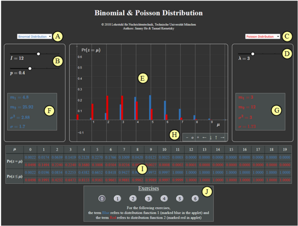
(A) Vorauswahl für blauen Parametersatz
(B) Parametereingabe $I$ und $p$ per Slider
(C) Vorauswahl für roten Parametersatz
(D) Parametereingabe $\lambda$ per Slider
(E) Graphische Darstellung der Verteilungen
(F) Momentenausgabe für blauen Parametersatz
(G) Momentenausgabe für roten Parametersatz
(H) Variation der grafischen Darstellung
$\hspace{1.5cm}$„$+$” (Vergrößern),
$\hspace{1.5cm}$ „$-$” (Verkleinern)
$\hspace{1.5cm}$ „$\rm o$” (Zurücksetzen)
$\hspace{1.5cm}$ „$\leftarrow$” (Verschieben nach links), usw.
( I ) Ausgabe von ${\rm Pr} (z = \mu)$ und ${\rm Pr} (z \le \mu)$
(J) Bereich für die Versuchsdurchführung
Andere Möglichkeiten zur Variation der grafischen Darstellung:
- Gedrückte Shifttaste und Scrollen: Zoomen im Koordinatensystem,
- Gedrückte Shifttaste und linke Maustaste: Verschieben des Koordinatensystems.
About the Authors
Dieses interaktive Berechnungstool wurde am Lehrstuhl für Nachrichtentechnik der Technischen Universität München konzipiert und realisiert.
- Die erste Version wurde 2009 von Alexander Happach im Rahmen seiner Diplomarbeit mit „FlashMX–Actionscript” erstellt (Betreuer: Günter Söder).
- 2020 wurde das Programm von Andre Schulz (Bachelorarbeit LB, Betreuer: Benedikt Leible und Tasnád Kernetzky ) unter „HTML5” neu gestaltet.
