Exercise 4.4: Modulation in LTE
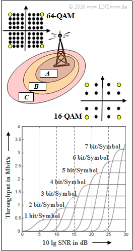
With LTE, the scheduler selects the appropriate modulation method depending on the nature of the environment and the distance of the user from the base station. In this task, we consider various QAM procedures, namely
- 4–QAM with $b\text{ = 2 bit/Symbol}$,
- 16– QAM with $b\text{ = 4 bit/Symbol}$,
- 64– QAM with $b\text{ = 6 bit/Symbol}$.
Formally, these procedures can be described as "$b^{2}$-QAM" . The signal space constellations for 16-QAM and 64-QAM are shown on the right. The yellow dots indicate the 4-QAMs.
The lower diagram from [MG08] shows for different $b$–values the throughput depending on the signal-to-noise ratio ⇒ $10 \cdot {\rm lg \ SNR}$. You can see that for a very good channel $($also very large $\rm SNR)$ the throughput is approximately proportional to $b$ .
Notes:
- This task belongs to the chapter Bitübertragungsschicht bei LTE.
- Reference is made in particular to the pages Modulation bei LTE as well as Digitale Modulationsverfahren in the book „Modulation Methods”.
- The areas $\rm A$, $\rm B$ and $\rm C$ shown in the above sketch are to be assigned to the modulation methods 4-QAM, 16-QAM and 64-QAM in the subtask '(1)’.
- The literature reference [MG08] refers to:
Myung, H.; Goodman, D.: Single Carrier FDMA - A New Air Interface for Long Term Evolution. West Sussex: John Wiley & Sons, 2008.
Questionnaire
Sample solution
(1) Correct is only the solution 2:
- Im sendernahen Gebiet $\rm A$ herrschen üblicherweise die besten Empfangsbedingungen vor. Hier kann das Modulationsverfahren 64–QAM verwendet werden, das bei idealen Bedingungen den höchsten Durchsatz ermöglicht, aber bei sinkendem SNR auch am meisten degradiert.
- Für das senderferne Gebiet $\rm C$ ist dagegen die 64–QAM nicht geeignet. Hier verwendet man besser das niederststufigste Modulationsverfahren 4–QAM.
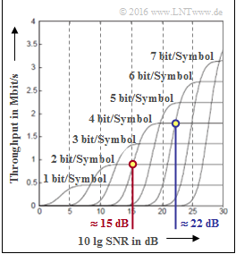
(2) Zu vergleichen sind hier die beiden mit „$2 \ \rm bit/Symbol$” und „$4 \ \rm bit/Symbol$” beschrifteten Kurven.
- Der Schnittpunkt liegt bei $10 \cdot {\rm lg \ SNR_{1}}\hspace{0.15cm}\underline{ \approx 15 \ \rm dB}$.
- Daraus folgt direkt: Die 16–QAM führt nur dann zu einem größeren Durchsatz als die 4–QAM, wenn $10 \cdot {\rm lg \ SNR} > 15 \ \rm dB$ ist.
(3) Das Ergebnis $10 \cdot {\rm lg \ SNR_{2}}\hspace{0.15cm}\underline{ \approx 22 \ \rm dB}$ ergibt sich aus dem Schnittpunkt der beiden Kurven „$4 \ \rm bit/Symbol$” und „$6 \ \rm bit/Symbol$”.
(4) Aus der Darstellung ist zu erkennen, dass mit 4–QAM ($2 \ \rm bit/Symbol$) der Durchsatz (nahezu) $0$ ist.
- Die QPSK ist bei diesem Vergleich identisch mit der 4–QAM und somit ebenfalls ungeeignet.
- Besser wäre Binary Phase Shift Keying (BPSK), was der untersten Kurve „$1 \ \rm bit/Symbol$” entspricht ⇒ Lösungsvorschlag 1.

