Exercise 4.4Z: Pointer Diagram for SSB-AM
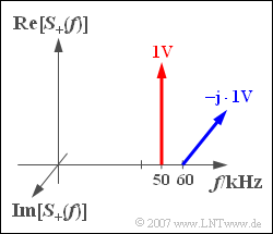
The analytical signal $s_+(t)$ with the line spectrum
- $$S_{+}(f) = {\rm 1 \hspace{0.05cm} V} \cdot\delta (f - f_{\rm 50})- {\rm j} \cdot {\rm 1 \hspace{0.05cm} V} \cdot\delta (f - f_{\rm 60})$$
is to be considered. Here $f_{50}$ and $f_{60}$ are abbreviations for the frequencies $50 \ \text{kHz}$ and $60 \ \text{kHz}$, respectively..
This analytical signal could occur, for example, with the single sideband amplitude modulation (SSB-AM) of a sinusoidal message signal $($Frequenz $f_{\rm N} = 10 \ \text{kHz})$ with a cosinusoidal carrier signal $(f_{\rm T} = 50 \ \text{kHz})$ , whereby only the upper sideband is transmitted (USB-Modulation).
However, the analytical signal could also result from a LSB-Modulation modulation of the same sinusoidal signal if a sinusoidal carrier signal with carrier frequency $f_{\rm T} = 60 \ \text{kHz}$ is used.
Hints:
- This exercise belongs to the chapter Analytical Signal and Its Spectral Function.
- You can check your solution with the interaction module Physikalisches Signal & Analytisches Signal .
Questions
Solution
(1) The analytical signal is generally:
- $$s_{+}(t) = {\rm 1 \hspace{0.05cm} V} \cdot {\rm e}^{{\rm j}\hspace{0.05cm} \omega_{\rm 50}\hspace{0.05cm} t } - {\rm j}\cdot{\rm 1 \hspace{0.05cm} V} \cdot {\rm e}^{{\rm j}\hspace{0.05cm} \omega_{\rm 60} \hspace{0.05cm} t }.$$
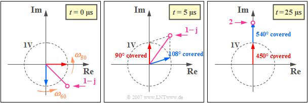
At time $t = 0$ the complex exponential functions each take the value $1$ and one obtains (see left graph):
- $\text{Re}[s_+(t = 0)] \; \underline{= +1\ \text{V}}$,
- $\text{Im}[s_+(t = 0)]\; \underline{ = \,-\hspace{-0.08cm}1\ \text{V}}$.
(2) For the analytical signal it can also be written:
- $$s_{+}(t) = {\rm 1 \hspace{0.05cm} V} \cdot \cos({ \omega_{\rm 50}\hspace{0.05cm} t }) + {\rm j} \cdot{\rm 1 \hspace{0.05cm} V} \cdot \sin({ \omega_{\rm 50}\hspace{0.05cm} t }) - {\rm j} \cdot {\rm 1 \hspace{0.05cm} V} \cdot \cos({ \omega_{\rm 60}\hspace{0.05cm} t }) + {\rm 1 \hspace{0.05cm} V} \cdot \sin({ \omega_{\rm 60}\hspace{0.05cm} t }).$$
The real part of this describes the actual, physical signal:
- $$s(t) = {\rm 1 \hspace{0.05cm} V} \cdot \cos({ \omega_{\rm 50}\hspace{0.05cm} t }) + {\rm 1 \hspace{0.05cm} V} \cdot \sin({ \omega_{\rm 60}\hspace{0.05cm} t }).$$
Correct is the proposed solution 3:
- Considering the $50 \ \text{kHz-Cosinussignals}$ cosine signal alone, the first zero crossing would occur at $t_1 = T_0/4$ , i.e. after $5 \ {\rm µ s}$, where $T_0 = 1/f_{50} = 20 \ {\rm µ s}$ denotes the period duration of this signal.
- The sinusoidal signal with the frequency $60 \ \text{kHz}$ is positive during the entire first half-wave $(0 \, \text{...} \, 8.33\ {\rm µ s})$ .
- Due to the plus sign, the first zero crossing of $s(t) \ \Rightarrow \ t_1 > 5\ {\rm µ s}$ is delayed.
- The middle graph shows the analytical signal at time $t = T_0/4$, when the red carrier would have its zero crossing.
- The zero crossing of the violet cumulative pointer only occurs when it points in the direction of the imaginary axis. Then $s(t_1) = \text{Re}[s_+(t_1)] = 0$.
(3) The maximum value of $|s_+(t)|$ is reached when both pointers point in the same direction. The amount of the sum pointer is then equal to the sum of the two individual pointers; i.e. $\underline {2\ \text{ V}}$.
This case is reached for the first time when the faster pointer with angular velocity $\omega_{60}$ has caught up its "lag" of $90^{\circ} \; (\pi /2)$ with the slower pointer ($\omega_{50}$) :
- $$\omega_{\rm 60} \cdot t_2 - \omega_{\rm 50}\cdot t_2 = \frac{\pi}{2} \hspace{0.3cm} \Rightarrow\hspace{0.3cm}t_2 = \frac{\pi/2}{2\pi (f_{\rm 60}- f_{\rm 50})} = \frac{1}{4 \cdot(f_{\rm 60}- f_{\rm 50})}\hspace{0.15 cm}\underline{= {\rm 25 \hspace{0.05cm} {\rm µ s}}}.$$
- At this point, the two pointers have made $5/4$ bzw. $6/4$ revolutions respectively and both point in the direction of the imaginary axis (see right graph).
- The actual, physical signal $s(t)$ – i.e. the real part of $s_+(t)$ – is therefore zero at this moment.
(4) The condition for $|s_+(t_3)| = 0$ is that there is a phase offset of $180^\circ$ between the two equally long pointers so that they cancel each other out.
- This further means that the faster pointer has rotated $3\pi /2$ further than the $50 \ \text{kHz-component}$.
- Analogous to the sample solution of sub-task (3) , the following therefore applies:
- $$t_3 = \frac{3\pi/2}{2\pi (f_{\rm 60}- f_{\rm 50})} \hspace{0.15 cm}\underline{= {\rm 75 \hspace{0.05cm} {\rm µ s}}}.$$

