Contents
Impulse Response
On the page Das erste Fourierintegral in the book ”Signal Representation” it was explained that for any deterministic signa $x(t)$ a spectral function $X(f)$ can be given with the help of the Fourier transform. Often $X(f)$ is referred to as the spectrum in short.
However, all information about the spectral function is already contained in the time domain representation, even if not always immediately recognisable. The same facts apply to linear time-invariant systems.
$\text{Definition:}$ The most important descriptive quantity of a linear time-invariant system in the time domain is the inverse Fourier transform of $H(f)$, which is called the impulse response :
- $$h(t) = \int_{-\infty}^{+\infty}H(f) \cdot {\rm e}^{\hspace{0.05cm}{\rm j}2\pi ft}\hspace{0.15cm} {\rm d}f.$$
The following should be noted in this regard:
- The frequency response $H(f)$ and the impulse response $h(t)$ are equivalent descriptive quantities that contain exactly the same information about the LTI-system.
- If the dirac-shaped input signal $x(t) = δ(t)$ is used, then $X(f) = 1$ is to be set and $Y(f) = H(f)$ or $y(t) = h(t)$ are valid.
- The term ”impulse response” reflects this statement: $h(t)$ is the response of the system to a (Dirac delta) function as an input signal.
- The above definition suggests that any impulse response must have the unit $\text{Hz = 1/s}$ .
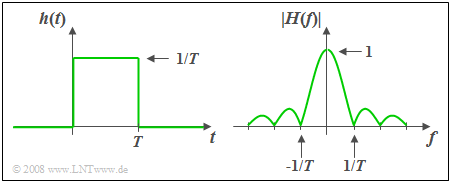
$\text{Example 1:}$ The impulse response $h(t)$ of the so-called slit–lowpass is constant over a time interval $T$ and is zero outside this time interval.
- The associated amplitude response as the magnitude of the frequency response is
- $$\vert H(f)\vert = \vert {\rm si}(\pi fT)\vert .$$
- The area over $h(t)$ is equal to $H(f = 0) = 1$. It follows that:
In the range $ 0 < t < T$ the impulse response must be equal to $1/T$ . - The phase response is given by
- $$b(f) = \left\{ \begin{array}{l} \hspace{0.25cm}\pi/T \\ - \pi/T \\ \end{array} \right.\quad \quad\begin{array}{*{20}c} \text{für} \\ \text{für} \\ \end{array}\begin{array}{*{20}c}{\left \vert \hspace{0.05cm} f\hspace{0.05cm} \right \vert > 0,} \\{\vert \hspace{0.05cm} f \hspace{0.05cm} \vert < 0.} \\\end{array}$$
- For $h(t)$ that are symmetric about $t = 0$ (i.e. noncausal) $b(f)=0$ holds.
Some Laws of the Fourier Transformation
The Gesetzmäßigkeiten der Fouriertransformation have already been explained in detail in the book ”Signal Representation”.
The following is a short summary, where $H(f)$ describes the frequency response of an LTI-system and whose inverse Fourier transform $h(t)$ is the impulse response. The laws and principles are applied more frequently in the Aufgaben for this chapter ”Systemtheoretische Grundlagen”.
Here, we also refer to the didactic video Gesetzmäßigkeiten der Fouriertransformation.
In the following equations the short symbol of the Fourier transformation is used. The filled-out circle indicates the spectral domain, the white one the time domain.
- Multiplikcation with a constant faktor:
- $$k \cdot H(f)\bullet\!\!-\!\!\!-\!\!\!-\!\!\circ\,k \cdot h(t).$$
- For $k \lt 1$ one deals with attenuation, while $k \gt 1$ stands for amplification.
- Similarity Theorem:
- $$H({f}/{k})\bullet\!\!-\!\!\!-\!\!\!-\!\!\circ\,|k| \cdot h(k\cdot t).$$
- This implies: Compression $(k < 1)$ of the frequency response results in a wider and lower impulse response.
- Dilation $(k > 1)$ of $H(f)$ makes $h(t)$ narrower and higher.
- Displacement Theorem in the frequency and time domain:
- $$H(f - f_0) \bullet\!\!-\!\!\!-\!\!\!-\!\!\circ\, h( t )\cdot {\rm e}^{\hspace{0.05cm}{\rm j}2\pi f_0 t},\hspace{0.9cm}
H(f) \cdot {\rm e}^{-{\rm j}2\pi ft_0}\bullet\!\!-\!\!\!-\!\!\!-\!\!\circ\, h( t- t_0 ).$$
- A shift by $t_0$ (transit time) thus leads to the multiplication by a complex exponential function in the frequency domain.
- The amplitude response $|H(f)|$ is not changed by this.
- Differentiation Theorem in the frequency and time domain:
- $$\frac{1}{{{\rm j}2\pi }} \cdot \frac{{{\rm d}H( f )}}{{{\rm d}f}} \bullet\!\!-\!\!\!-\!\!\!-\!\!\circ\,- t \cdot h( t ),\hspace{0.9cm} {\rm j}\cdot 2\pi f \cdot H( f ){}\bullet\!\!-\!\!\!-\!\!\!-\!\!\circ\, \frac{{{\rm d}h( t )}}{{\rm d}t}.$$
- A differentiating element in the LTI-system leads to a multiplication by ${\rm j}\cdot 2πf$ in the frequency domain and thus among other things to a phase rotation by $90^{\circ}$.
Causal Systems
$\text{Definition:}$ An LTI-system is said to be causal, if the impulse response $h(t)$ – that is, the inverse Fourier transform of the frequency response $H(f)$ – satisfies the following condition:
- $$h(t) = 0 \hspace{0.25cm}{\rm f\ddot{u}r}\hspace{0.25cm} t < 0.$$
$\text{Please note:}$ Any realisable system is causal.
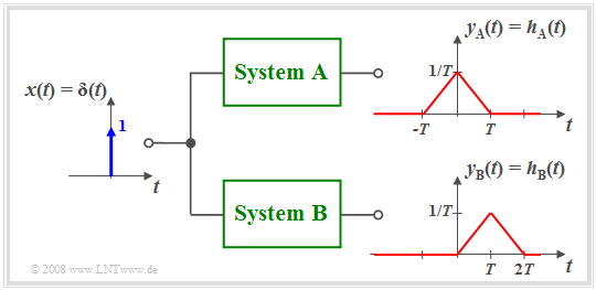
$\text{Example 2:}$ The diagram illustrates the difference between the noncausal system $\rm A$ and the causal system $\rm B$.
- In the system $\rm A$ the effect starts earlier $($at $t =\hspace{0.05cm} –T)$ than the cause $($Dirac delta function at $t = 0)$, which of course is not possible in practice.
- Almost all noncausal systems can be transformed into a feasible causal system using a runtime $\tau$ .
- For example, with $\tau = T$ the following holds:
- $$h_{\rm B}(t) = h_{\rm A}(t - T).$$
- All statements made so far apply for causal as well as noncausal systems.
- However, for the description of causal systems some specific properties can be used as explained in the third main chapter ”Description of Causal Realisable Systems” of this book .
In this first and the following second main chapter we mainly consider noncausal systems, since their mathematical description is usually simpler.
- So, the frequency response $H_{\rm A}(f)$ real,
- while for $H_{\rm B}(f)$ the additional term ${\rm e}^{–{\rm j2π}f\hspace{0.05cm}T}$ has to be considered.
Computation of the Output Signal
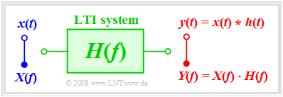
We consider the following problem: Let the input signal $x(t)$ and the frequency response $H(f)$ be known. The output signal $y(t)$ is to be determinded.
If the solution is to be determined in the frequency domain, first the spectrum $X(f)$ must be determined from the given input signal $x(t)$ via Fouriertransformation and multiplied by the frequency response $H(f)$ . By a Fourierrücktransformation of the product the signal $y(t)$ is obtained.
Here is a summary of the entire solution process:
- $${\rm 1.\,\, step\hspace{-0.1cm} :}\hspace{0.5cm} X(f)\bullet\!\!-\!\!\!-\!\!\!-\!\!\circ\, x( t )\hspace{1.55cm}{\rm input/spectrum},$$
- $${\rm 2.\,\, step\hspace{-0.1cm}:}\hspace{0.5cm}Y(f)= X(f) \cdot H(f) \hspace{0.82cm}{\rm output spectrum},$$
- $${\rm 3.\,\, step\hspace{-0.1cm}:}\hspace{0.5cm} y(t)\circ\!\!-\!\!\!-\!\!\!-\!\!\bullet\, Y(f )\hspace{1.55cm}{\rm output signal}.$$
Zum gleichen Ergebnis kommt man nach der Berechnung im Zeitbereich, indem man zunächst aus dem Frequenzgang $H(f)$ mittels Fourierrücktransformation die Impulsantwort $h(t)$ berechnet und anschließend die Faltungsoperation anwendet:
- $$y(t) = x (t) * h (t) = \int_{ - \infty }^{ + \infty } {x ( \tau )} \cdot h ( {t - \tau } ) \hspace{0.1cm}{\rm d}\tau.$$
- Die Ergebnisse sind bei beiden Vorgehensweisen identisch.
- Zweckmäßigerweise sollte man dasjenige Verfahren auswählen, das mit weniger Rechenaufwand zum Ziel führt.
$\text{Beispiel 3:}$ Am Eingang eines Spalt–Tiefpasses mit rechteckförmiger Impulsantwort der Breite $T$ (siehe $\text{Beispiel 1}$) liegt ein Rechteckimpuls $x(t)$ der Dauer $2T$ an.
In diesem Fall ist die direkte Berechnung im Zeitbereich günstiger:
- Die Faltung zweier unterschiedlich breiter Rechtecke $x(t)$ und $h(t)$ führt zum trapezförmigen Ausgangsimpuls $y(t)$.
- Man erkennt die Tiefpasseigenschaft des Filters an der endlichen Flankensteilheit von $y(t)$.
- Die Impulshöhe $3\text{ V}$ bleibt in diesem Beispiel erhalten, wegen
- $$H(f = 0) = 1/T · T = 1.$$
Step Response
$\text{Definitionen:}$ Eine in der Praxis oft verwendete Eingangsfunktion $x(t)$ zur Messung von $H(f)$ ist die Sprungfunktion
- $${\rm \gamma}(t) = \left\{ \begin{array}{l} \hspace{0.25cm}0 \\ 0.5 \\ \hspace{0.25cm} 1 \\ \end{array} \right.\quad \quad\begin{array}{*{20}c} \text{für} \\ \text{für}\\ \text{für} \\ \end{array}\begin{array}{*{20}c}{\vert \hspace{0.05cm} t\hspace{0.05cm} \vert < 0,} \\ {\vert \hspace{0.05cm}t\hspace{0.05cm} \vert = 0,} \\ {\vert \hspace{0.05cm} t \hspace{0.05cm} \vert > 0.} \\ \end{array}$$
Die Sprungantwort $\sigma(t)$ ist die Antwort des Systems, wenn man an den Eingang die Sprungfunktion $\gamma(t)$ anlegt:
- $$x(t) = {\rm \gamma}(t)\hspace{0.5cm}\Rightarrow \hspace{0.5cm} y(t) = {\rm \sigma}(t).$$
Die Berechnung im Frequenzbereich wäre hier etwas umständlich, denn man müsste dann folgende Gleichung anwenden:
- $${\rm \sigma}(t)\circ\!\!-\!\!\!-\!\!\!-\!\!\bullet\, X(f ) \cdot H(f) =\left({1}/{2}\cdot \delta(f) + \frac{1}{{\rm j}\cdot 2\pi f} \right) \cdot H(f).$$
Die Berechnung im Zeitbereich führt dagegen direkt zum Ergebnis:
- $${\rm \sigma}(t) = \int_{ - \infty }^{ t } {h ( \tau )} \hspace{0.1cm}{\rm d}\tau.$$
Bei kausalen Systemen gilt $h(\tau) = 0$ für $\tau \lt 0$, so dass die untere Integrationsgrenze in obiger Gleichung zu $\tau = 0$ gesetzt werden kann.
$\text{Beweis:}$ Das genannte Ergebnis ist auch aus folgendem Grunde einsichtig:
- Die Sprungfunktion $\gamma(t)$ hängt mit der Diracfunktion $\delta(t)$ wie folgt zusammen:
- $${\rm \gamma}(t) = \int_{ - \infty }^{ t } {\delta ( \tau )} \hspace{0.1cm}{\rm d}\tau.$$
- Da wir Linearität vorausgesetzt haben und die Integration eine lineare Operation darstellt, gilt auch für das Ausgangssignal der entsprechende Zusammenhang:
- $${\rm \sigma}(t) = \int_{ - \infty }^{ t } {h ( \tau )} \hspace{0.1cm}{\rm d}\tau.$$
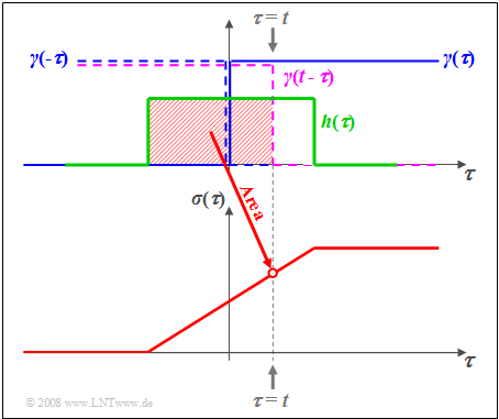
$\text{Beispiel 4:}$ Die Grafik verdeutlicht den Sachverhalt für die Rechteck–Impulsantwort $h(\tau)$.
- Die Abszisse wurde in $\tau$ umbenannt.
- Blau eingezeichnet ist die Sprungfunktion $\gamma(\tau)$.
- Durch Spiegelung und Verschiebung erhält man $\gamma(t - \tau)$ ⇒ violett gestrichelte Kurve.
- Die rot hinterlegte Fläche gibt somit die Sprungantwort $\sigma(\tau)$ zum Zeitpunkt $\tau = t$ an.
Exercise for the Chapter
Aufgabe 1.3: Gemessene Sprungantwort
Aufgabe 1.3Z: Exponentiell abfallende Impulsantwort
Aufgabe 1.4: Zum Tiefpass 2. Ordnung
Aufgabe 1.4Z: Alles rechteckförmig


