Exercise 3.5: Circuit with R, L and C
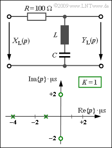
We consider a two-port network with the resistance $R = 100 \ \rm \Omega$ in the longitudinal branch, while in the transverse branch an inductance $L$ and a capacitance $C$ are connected in series. The pole–zero diagram is drawn below.
Note the normalization of the complex frequency $p = {\rm j} \cdot 2 \pi f$ to the value $1/T$ with $T = 1 \ \rm µ s$. As a consequence, for example the pole at $-1$ is at $-10^6 \cdot \ \rm 1/s$ in reality.
The residue theorem can be applied to compute time functions:
- For $N$ simple poles, the output $y(t)$ is composed of $N$ natural oscillations (residuals) .
- For a simple pole at $p_{{\rm x}i}$, the following holds for the residual:
- $${\rm Res} \bigg |_{p \hspace{0.05cm}= \hspace{0.05cm}p_{{\rm x}i}} \hspace{-0.7cm}\{Y_{\rm L}(p)\cdot {\rm e}^{p t}\}= Y_{\rm L}(p)\cdot (p - p_{{\rm x}i})\cdot {\rm e}^{\hspace{0.05cm}p \hspace{0.05cm}t} \bigg |_{p \hspace{0.05cm}= \hspace{0.05cm}p_{{\rm x}i}} \hspace{0.05cm} .$$
- However, this approach only works if the number $Z$ of zeros is less than $N$. In this exercise, for example if the step response $\sigma(t)$ is computed. In this case, $Z = 2$ and $N = 3$ hold since the step function at the input must additionally be taken into account by $X_{\rm L}(p) = 1/p$ .
- This approach does not work for the computation of the impulse response $h(t)$ due to $Z = N =2$ .
- Here, the fact that the integral over the impulse response $h(t)$ results in the step response $\sigma(t)$ can be considered.
Please note:
- The exercise belongs to the chapter Inverse Laplace Transform.
Questions
Solution
- At extremely low frequencies $(f \rightarrow 0)$, the capacitance $C$ has infinite resistance and at very high frequencies $(f \rightarrow \infty)$ the inductance $L$.
- In both cases, $Y(f) = X(f)$ ⇒ $H(f) = 1$ holds.
- In contrast, the LC series connection acts as a short circuit at the resonance frequency $f_0$ and $H(f = f_0) = 0$ holds.
- The followiong follows from the block diagram alone: It is a band-stop filter.
(2) The following $p$–transfer function $($without the normalization factor $1/T)$ is obtained from the pole–zero diagram:
- $$H_{\rm L}(p)= \frac {(p - {\rm j} \cdot 2)(p + {\rm j} \cdot 2)} {(p +1)(p +4 )}= \frac {p^2 +4} {p^2 + 5 \cdot p +4} \hspace{0.05cm} .$$
- The capacitance for the circuit is obtained considering the voltage divider properties with the reactance $p \cdot L$ of the inductance and the reactance $1/(p \cdot C)$ of the capacitance:
- $$H_{\rm L}(p)= \frac { p\cdot L +1/(pC) } {R + p \cdot L +1/(pC) }= \frac { p^2 +1/(pC) } {p^2 + p \cdot {R}/{L} +1/(pC) }\hspace{0.05cm} .$$
- Taking into account the normalization factor $1/T= 10^6 \cdot \rm 1/s$ and by comparison, the following is found:
- $${R}/{L} \hspace{0.25cm} = \hspace{0.2cm} 5 \cdot 10^{6 }\, {\rm 1/s} \hspace{0.3cm}\Rightarrow \hspace{0.3cm}L= \frac{100\, {\rm \Omega}}{5 \cdot 10^6 \, {\rm 1/s}}\hspace{0.15cm}\underline{= 20\,{\rm µ H} \hspace{0.05cm}} ,$$
- $${1}/({LC}) \hspace{0.25cm} = \hspace{0.2cm}4 \cdot 10^{12 }\, {\rm 1/s^2} \hspace{0.3cm}\Rightarrow \hspace{0.3cm}C= \frac{1}{4 \cdot 10^{12 }\, {\rm 1/s^2}\cdot 2 \cdot 10^{-5 }\, {\rm \Omega \cdot s} } \hspace{0.15cm}\underline{= 12.5\,{\rm nF}} \hspace{0.05cm} .$$
(3) The step function at the input is accounted for by $X_{\rm L}(p) = 1/p$ . This results in
- $$Y_{\rm L}(p)= \frac {p^2 +4} {p \cdot (p +1)\cdot(p +4 )} \hspace{0.05cm} $$
whereof the time function $y(t)$ can be determined by applying the residue theorem:
- $$y_1(t) \hspace{0.25cm} = \hspace{0.2cm} \frac {p^2 +4} { (p +1)\cdot(p +4 )} \cdot {\rm e}^{\hspace{0.05cm}p \hspace{0.05cm}t} \bigg |_{p \hspace{0.05cm}= \hspace{0.05cm}0}= 1 \hspace{0.05cm} ,$$
- $$ y_2(t) \hspace{0.25cm} = \hspace{0.2cm} \frac {p^2 +4} { p\cdot(p +4 )} \cdot {\rm e}^{\hspace{0.05cm}p \hspace{0.05cm}t} \bigg |_{p \hspace{0.05cm}= \hspace{0.05cm}-1}= - {5}/{3}\cdot {\rm e}^{ \hspace{0.05cm}-t} \hspace{0.05cm} ,$$
- $$ y_3(t) \hspace{0.25cm} = \hspace{0.2cm} \frac {p^2 +4} { p\cdot(p +1 )} \cdot {\rm e}^{\hspace{0.05cm}p \hspace{0.05cm}t} \bigg |_{p \hspace{0.05cm}= \hspace{0.05cm}-4}= {5}/{3}\cdot {\rm e}^{ \hspace{0.05cm}-4t}$$
- $$\Rightarrow \hspace{0.3cm}y(t)= y_1(t)+y_2(t)+y_3(t)= 1- {5}/{3}\cdot {\rm e}^{ \hspace{0.05cm}-t/T}+\ {5}/{3}\cdot {\rm e}^{ \hspace{0.05cm}-4t/T} \hspace{0.05cm} .$$
Here, it is taken into account that the constant $10^6 \cdot \rm 1/s$, which is not considered in this calculation, is compensated for by the time normalization to $T = 1 \ \rm µ s$ .
The signal values which are looked for are:
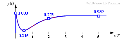
- $$y(t = 0) \hspace{0.05cm}\underline{= 1.000}\hspace{0.05cm}, \hspace{0.15cm}y(t = 0.5\,{\rm µ s}) \hspace{0.05cm}\underline{= 0.215}\hspace{0.05cm}, $$
- $$y(t = 2\,{\rm µ s}) \hspace{0.05cm}\underline{= 0.775}\hspace{0.05cm}, \hspace{0.15cm}y(t = 5\,{\rm µ s}) \hspace{0.05cm}\underline{= 0.989}\hspace{0.05cm}. $$
The graph shows the signal curve. The searched-for numerical values are inscribed again.
The following can be seen from this representation:
- Since extremely high frequencies are not affected by the system (band-stop filter), the jump from $0$ to $1$ with infinite edge steepness can also be seen in the output signal $y(t)$ .
- The limit of $y(t)$ for $t → \infty$ consequently also yields the value $1$ because of $H(f = 0) = 1$ .
- There is a drop in the signal curve due to the LC resonance frequency at $f_0 = 1/\pi$ (in $\rm MHz)$ .
- The signal minimum of $\approx 0.215$ is at approximately $t = 0.5 \ \rm µ s$.
(4) Suggested solutions 1 and 3 are correct:
- The impulse response $h(t)$ is obtained from the step response $\sigma(t)=y(t)$ by differentiation:
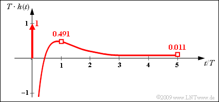
- $$h(t)= \frac{{\rm d}\hspace{0.1cm}y(t)}{{\rm d}t}= \delta (t) + \frac {5}{3T}\cdot {\rm e}^{ \hspace{0.05cm}-t/T}- \frac {20}{3T}\cdot {\rm e}^{ \hspace{0.05cm}-4t/T} \hspace{0.05cm} .$$
- The first suggested solution is thus correct since differentiation of a step function yields the Dirac function.
- The following numerical values are obtained for the continuous part of $h(t)$ :
- $$T \cdot h(t = 0 )\hspace{0.25cm} = \hspace{0.2cm} {5}/{3}- {20}/{3}= -5 \hspace{0.05cm} ,$$
- $$ T \cdot h(t = T )\hspace{0.25cm} = \hspace{0.2cm} {5}/{3}\cdot {\rm e}^{ \hspace{0.05cm}-1}- {20}/{3}\cdot {\rm e}^{ \hspace{0.05cm}-4}= {5}/{3}\cdot 0.368- {20}/{3}\cdot 0.018\approx 0.491 \hspace{0.05cm} .$$
- Since $h(t)$ tends to zero in the limiting case for $t → \infty$, the third proposed solution is also correct in contrast to the second one.
- The curve of $h(t)$ is shown in the adjacent diagram.


