Exercise 3.9: Circular Arc and Parabola
We now consider the frequency modulation of a cosine source signal
- $$q(t) = A_{\rm N} \cdot \cos(2 \pi \cdot f_{\rm N} \cdot t )$$
with amplitude $A_{\rm N} = 1 \ \rm V$ and frequency $f_{\rm N} = 5 \ \rm kHz$.
- The modulation index (phase deviation) is $η = 2.4$.
- The corresponding low-pass signal with normalized carrier amplitude $(A_{\rm T} = 1)$ is:
- $$ s_{\rm TP}(t) = \sum_{n = - \infty}^{+\infty}{\rm J}_n (\eta) \cdot {\rm e}^{\hspace{0.05cm}{\rm j} \hspace{0.05cm}\cdot \hspace{0.05cm}n\hspace{0.05cm}\cdot \hspace{0.05cm}\omega_{\rm N} \hspace{0.05cm}\cdot \hspace{0.05cm} t}.$$
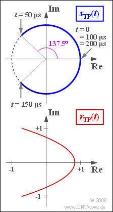
- This represents an arc. Within the period $T_{\rm N} = 1/f_{\rm N} = 200 \ \rm µ s$ the following phase angles result:
- $$ \phi(0) = 0, \hspace{0.2cm}\phi(0.25 \cdot T_{\rm N}) = \eta, \hspace{0.2cm}\phi(0.5 \cdot T_{\rm N})= 0,\hspace{0.2cm} \phi(0.75 \cdot T_{\rm N})= -\eta,\hspace{0.2cm}\phi(T_{\rm N})= 0.$$
- Theoretically, the channel bandwidth required to transmit this signal is infinite.
However, if the bandwidth is limited to $B_{\rm K} = 25 \ \rm kHz$, for example,the equivalent low-pass signal of the received signal can be described as follows:
- $$r_{\rm TP}(t) = \sum_{n = - 2}^{+2}{\rm J}_n (\eta) \cdot {\rm e}^{\hspace{0.05cm}{\rm j} \hspace{0.05cm}\cdot \hspace{0.05cm}n\hspace{0.05cm}\cdot \hspace{0.05cm}\omega_{\rm N} \hspace{0.05cm}\cdot \hspace{0.05cm} t}.$$
In this case, the result is a parabolic locus curve
- $$ y^2 + a \cdot x + b = 0,$$
which will be analyzed in this task.
Hints:
- This exercise belongs to the chapter Frequency Modulation.
- Reference is also made to the chapter Phase Modulation and particularly to the section Signal characteristics with frequency modulation.
- During calculation, assume the following values of the Bessel function:
- $${\rm J}_0 (2.4) \approx 0, \hspace{0.2cm}{\rm J}_1 (2.4) = -{\rm J}_{-1} (2.4)\approx 0.52, \hspace{0.2cm}{\rm J}_2 (2.4) = {\rm J}_{-2} (2.4)\approx 0.43.$$
Question
Solution
- $$ \eta = \frac{K_{\rm FM} \cdot A_{\rm N}}{ \omega_{\rm N}} \hspace{0.3cm}\Rightarrow \hspace{0.3cm} K_{\rm FM} = \frac{2 \pi \cdot f_{\rm N }\cdot \eta}{ A_{\rm N}} = \frac{2 \pi \cdot 5 \cdot 10^3 \,{\rm Hz}\cdot 2.4}{ 1\,{\rm V}} \hspace{0.15cm}\underline {\approx 7.54 }\cdot 10^4 \,\,{\rm V}^{-1}{\rm s}^{-1}\hspace{0.05cm}.$$
(2) Die angegebene Gleichung für das äquivalente TP–Signal lautet in ausgeschriebener Form mit $γ = ω_{\rm N} · t$ unter Berücksichtigung von ${\rm J}_{–1} = –{\rm J}_1$ und ${\rm J}_{–2} = {\rm J}_2$:
- $$r_{\rm TP}(t) = {\rm J}_0 + \left[ {\rm e}^{\hspace{0.05cm}{\rm j} \hspace{0.05cm}\cdot \hspace{0.05cm} \gamma} - {\rm e}^{\hspace{0.05cm}{-\rm j} \hspace{0.05cm}\cdot \hspace{0.05cm} \gamma} \right]\cdot {\rm J}_1 \hspace{0.27cm} +\left[ {\rm e}^{\hspace{0.05cm}{\rm j} \hspace{0.05cm}\cdot \hspace{0.05cm} 2\gamma} + {\rm e}^{\hspace{0.05cm}{-\rm j} \hspace{0.05cm}\cdot \hspace{0.05cm} 2\gamma} \right]\cdot {\rm J}_2 = {\rm J}_0 + 2 \cdot {\rm j} \cdot {\rm J}_1 \cdot \sin (\gamma)+ 2 \cdot {\rm J}_2 \cdot \cos (2\gamma)\hspace{0.05cm} .$$
- Somit ergibt sich für den Realteil allgemein bzw. für $η = 2.4$, das heißt ${\rm J}_0 = 0$ und ${\rm J}_2 = 0.43$:
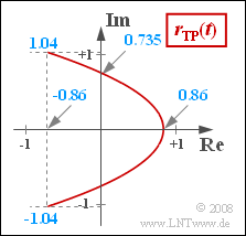
- $$ x(t) = {\rm J}_0 + 2 \cdot {\rm J}_2 \cdot \cos (2 \omega_{\rm N} t ) = 2 \cdot {\rm J}_2 \cdot \cos (2 \omega_{\rm N} t ) \hspace{0.3cm} \Rightarrow \hspace{0.3cm} x_{\rm max} = 2 \cdot {\rm J}_2\hspace{0.15cm}\underline { = 0.86}, \hspace{0.3cm} x_{\rm min} = -x_{\rm max} \hspace{0.15cm}\underline {= -0.86}\hspace{0.05cm}.$$
(3) Entsprechend dem Ergebnis der Teilaufgabe (2) erhält man für den Imaginärteil $({\rm J}_1 = 0.52)$:
- $$y(t) = 2 \cdot {\rm J}_1 \cdot \sin ( \omega_{\rm N} t )\hspace{0.3cm}\Rightarrow \hspace{0.3cm} y_{\rm max} =2 \cdot {\rm J}_1\hspace{0.15cm}\underline { = 1.04}\hspace{0.05cm}, \hspace{0.3cm} y_{\rm min} = -y_{\rm max}\hspace{0.15cm}\underline { = -1.04}\hspace{0.05cm}.$$
(4) Der Imaginärteil ist zu diesen Zeitpunkten jeweils Null und damit auch die Phasenfunktion:
- $$ϕ(t = n · T_{\rm N}/2)\hspace{0.15cm}\underline{= 0}.$$
- Diesen Sachverhalt erkennt man auch aus der Skizze auf der Angabenseite.
(5) Aus der Skizze ist bereits zu erkennen, dass der Phasenwinkel beispielsweise für $t = T_{\rm N}/4$ seinen Maximalwert erreicht.
- Dieser kann mit $y_{\rm max} = 1.04$ und $x_{\rm min} = -0.86$ wie folgt berechnet werden:
- $$\phi_{\rm max} = \arctan \frac{y_{\rm max}}{x_{\rm min}} = \arctan (-1.21) = 180^\circ - 50.4^\circ \hspace{0.15cm}\underline {= 129.6^\circ} \hspace{0.05cm}.$$
- Ohne Bandbegrenzung würde sich hier der Phasenwinkel $ϕ(t = T_{\rm N}/4) = η = 2.4 = 137.5^\circ$ ergeben.
- Die maximale Abweichung des Sinkensignals vom Quellensignal tritt somit beispielsweise zur Zeit $t = T_{\rm N}/4$ auf.
(6) Mit $γ = ω_{\rm N} · t$ und $\cos(2γ) = 1 - 2 · \cos^2(γ)$ kann für Real– und Imaginärteil geschrieben werden:
- $$x = {\rm J}_0 + 4 \cdot {\rm J}_2 \cdot \cos^2 (\gamma) - 2 \cdot {\rm J}_2\hspace{0.05cm},\hspace{0.3cm} y = 2 \cdot {\rm J}_1 \cdot \sin (\gamma) \hspace{0.05cm}.$$
- Diese Gleichungen können wie folgt umgeformt werden:
- $$\cos^2 (\gamma) =\frac{x-{\rm J}_0 + 2 \cdot {\rm J}_2 }{4 \cdot {\rm J}_2} \hspace{0.05cm},\hspace{0.3cm} \sin^2 (\gamma) = \frac{y^2 }{4 \cdot {\rm J}_1^2}$$
$$\Rightarrow \hspace{0.3cm} \frac{y^2 }{4 \cdot {\rm J}_1^2} + \frac{x-{\rm J}_0 + 2 \cdot {\rm J}_2 }{4 \cdot {\rm J}_2} =1 \hspace{0.3cm} \Rightarrow \hspace{0.3cm} {y^2 } + \frac{{\rm J}_1^2}{ {\rm J}_2} \cdot x + {{\rm J}_1^2} \cdot \left ( 2 - \frac{{\rm J}_0}{ {\rm J}_2} \right ) =0\hspace{0.05cm}.$$
- Damit lauten die Parabelparameter für $ {\rm J}_0 = 0$:
- $$a = \frac{{\rm J}_1^2}{ {\rm J}_2} \hspace{0.15cm}\underline {\approx 0.629}, \hspace{0.3cm} b = 2 \cdot {\rm J}_1^2 \hspace{0.15cm}\underline {\approx 0.541} \hspace{0.05cm}.$$
- Zur Kontrolle verwenden wir $y = 0$ ⇒ $ x_{\rm max} = {b}/{a} = 2 \cdot {\rm J}_2 = 0.86 \hspace{0.05cm}.$
- Die Werte bei $x = 0$ sind somit: $y_0 = \pm \sqrt{2} \cdot {\rm J}_1 \approx 0.735 \hspace{0.05cm}.$

