Exercise 3.9: Circular Arc and Parabola
We now consider the frequency modulation of a cosine source signal
- $$q(t) = A_{\rm N} \cdot \cos(2 \pi \cdot f_{\rm N} \cdot t )$$
with amplitude $A_{\rm N} = 1 \ \rm V$ and frequency $f_{\rm N} = 5 \ \rm kHz$.
- The modulation index (phase deviation) is $η = 2.4$.
- The corresponding low-pass signal with normalized carrier amplitude $(A_{\rm T} = 1)$ is:
- $$ s_{\rm TP}(t) = \sum_{n = - \infty}^{+\infty}{\rm J}_n (\eta) \cdot {\rm e}^{\hspace{0.05cm}{\rm j} \hspace{0.05cm}\cdot \hspace{0.05cm}n\hspace{0.05cm}\cdot \hspace{0.05cm}\omega_{\rm N} \hspace{0.05cm}\cdot \hspace{0.05cm} t}.$$
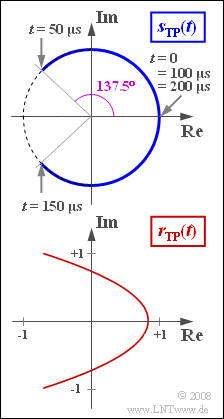
- This represents an arc. Within the period $T_{\rm N} = 1/f_{\rm N} = 200 \ \rm µ s$ the following phase angles result:
- $$ \phi(0) = 0, \hspace{0.2cm}\phi(0.25 \cdot T_{\rm N}) = \eta, \hspace{0.2cm}\phi(0.5 \cdot T_{\rm N})= 0,\hspace{0.2cm} \phi(0.75 \cdot T_{\rm N})= -\eta,\hspace{0.2cm}\phi(T_{\rm N})= 0.$$
- Theoretically, the channel bandwidth required to transmit this signal is infinite.
However, if the bandwidth is limited to $B_{\rm K} = 25 \ \rm kHz$, for example, the equivalent low-pass signal of the received signal can be described as follows:
- $$r_{\rm TP}(t) = \sum_{n = - 2}^{+2}{\rm J}_n (\eta) \cdot {\rm e}^{\hspace{0.05cm}{\rm j} \hspace{0.05cm}\cdot \hspace{0.05cm}n\hspace{0.05cm}\cdot \hspace{0.05cm}\omega_{\rm N} \hspace{0.05cm}\cdot \hspace{0.05cm} t}.$$
In this case, the result is a parabolic locus curve
- $$ y^2 + a \cdot x + b = 0,$$
which will be analyzed in this task.
Hints:
- This exercise belongs to the chapter Frequency Modulation.
- Reference is also made to the chapter Phase Modulation and particularly to the section Signal characteristics with frequency modulation.
- During calculation, assume the following values of the Bessel function:
- $${\rm J}_0 (2.4) \approx 0, \hspace{0.2cm}{\rm J}_1 (2.4) = -{\rm J}_{-1} (2.4)\approx 0.52, \hspace{0.2cm}{\rm J}_2 (2.4) = {\rm J}_{-2} (2.4)\approx 0.43.$$
Question
Solution
- $$ \eta = \frac{K_{\rm FM} \cdot A_{\rm N}}{ \omega_{\rm N}} \hspace{0.3cm}\Rightarrow \hspace{0.3cm} K_{\rm FM} = \frac{2 \pi \cdot f_{\rm N }\cdot \eta}{ A_{\rm N}} = \frac{2 \pi \cdot 5 \cdot 10^3 \,{\rm Hz}\cdot 2.4}{ 1\,{\rm V}} \hspace{0.15cm}\underline {\approx 7.54 }\cdot 10^4 \,\,{\rm V}^{-1}{\rm s}^{-1}\hspace{0.05cm}.$$
(2) The equation given for the equivalent low-pass signal when $γ = ω_{\rm N} · t$ and considering ${\rm J}_{–1} = –{\rm J}_1$ and ${\rm J}_{–2} = {\rm J}_2$, is written out as:
- $$r_{\rm TP}(t) = {\rm J}_0 + \left[ {\rm e}^{\hspace{0.05cm}{\rm j} \hspace{0.05cm}\cdot \hspace{0.05cm} \gamma} - {\rm e}^{\hspace{0.05cm}{-\rm j} \hspace{0.05cm}\cdot \hspace{0.05cm} \gamma} \right]\cdot {\rm J}_1 \hspace{0.27cm} +\left[ {\rm e}^{\hspace{0.05cm}{\rm j} \hspace{0.05cm}\cdot \hspace{0.05cm} 2\gamma} + {\rm e}^{\hspace{0.05cm}{-\rm j} \hspace{0.05cm}\cdot \hspace{0.05cm} 2\gamma} \right]\cdot {\rm J}_2 = {\rm J}_0 + 2 \cdot {\rm j} \cdot {\rm J}_1 \cdot \sin (\gamma)+ 2 \cdot {\rm J}_2 \cdot \cos (2\gamma)\hspace{0.05cm} .$$
- Thus, for the real part in general, including for $η = 2.4$, that is, ${\rm J}_0 = 0$ and ${\rm J}_2 = 0.43$:
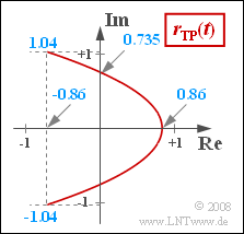
- $$ x(t) = {\rm J}_0 + 2 \cdot {\rm J}_2 \cdot \cos (2 \omega_{\rm N} t ) = 2 \cdot {\rm J}_2 \cdot \cos (2 \omega_{\rm N} t ) \hspace{0.3cm} \Rightarrow \hspace{0.3cm} x_{\rm max} = 2 \cdot {\rm J}_2\hspace{0.15cm}\underline { = 0.86}, \hspace{0.3cm} x_{\rm min} = -x_{\rm max} \hspace{0.15cm}\underline {= -0.86}\hspace{0.05cm}.$$
(3) According to the result of question (2) we get an imginary part $({\rm J}_1 = 0.52)$ of:
- $$y(t) = 2 \cdot {\rm J}_1 \cdot \sin ( \omega_{\rm N} t )\hspace{0.3cm}\Rightarrow \hspace{0.3cm} y_{\rm max} =2 \cdot {\rm J}_1\hspace{0.15cm}\underline { = 1.04}\hspace{0.05cm}, \hspace{0.3cm} y_{\rm min} = -y_{\rm max}\hspace{0.15cm}\underline { = -1.04}\hspace{0.05cm}.$$
(4) The imaginary part is zero at each of these time points and so is the phase function:
- $$ϕ(t = n · T_{\rm N}/2)\hspace{0.15cm}\underline{= 0}.$$
- This fact can also be seen from the sketch on the exercise page.
(5) From the sketch it can already be seen that the phase angle reaches its maximum value at $t = T_{\rm N}/4$ , for example.
- This can be calculated with $y_{\rm max} = 1.04$ and $x_{\rm min} = -0.86$ as follows:
- $$\phi_{\rm max} = \arctan \frac{y_{\rm max}}{x_{\rm min}} = \arctan (-1.21) = 180^\circ - 50.4^\circ \hspace{0.15cm}\underline {= 129.6^\circ} \hspace{0.05cm}.$$
- Without band-limiting, the phase angle here would be $ϕ(t = T_{\rm N}/4) = η = 2.4 = 137.5^\circ$ .
- Thus, the maximum deviation of the sink signal from the source signal occurs at time $t = T_{\rm N}/4$ , for example.
(6) Using $γ = ω_{\rm N} · t$ and $\cos(2γ) = 1 - 2 · \cos^2(γ)$ the real and imaginary parts can be written as:
- $$x = {\rm J}_0 + 4 \cdot {\rm J}_2 \cdot \cos^2 (\gamma) - 2 \cdot {\rm J}_2\hspace{0.05cm},\hspace{0.3cm} y = 2 \cdot {\rm J}_1 \cdot \sin (\gamma) \hspace{0.05cm}.$$
- These equations can be rearranegd:
- $$\cos^2 (\gamma) =\frac{x-{\rm J}_0 + 2 \cdot {\rm J}_2 }{4 \cdot {\rm J}_2} \hspace{0.05cm},\hspace{0.3cm} \sin^2 (\gamma) = \frac{y^2 }{4 \cdot {\rm J}_1^2}$$
$$\Rightarrow \hspace{0.3cm} \frac{y^2 }{4 \cdot {\rm J}_1^2} + \frac{x-{\rm J}_0 + 2 \cdot {\rm J}_2 }{4 \cdot {\rm J}_2} =1 \hspace{0.3cm} \Rightarrow \hspace{0.3cm} {y^2 } + \frac{{\rm J}_1^2}{ {\rm J}_2} \cdot x + {{\rm J}_1^2} \cdot \left ( 2 - \frac{{\rm J}_0}{ {\rm J}_2} \right ) =0\hspace{0.05cm}.$$
- Thus, the parabolic parameters for $ {\rm J}_0 = 0$ are:
- $$a = \frac{{\rm J}_1^2}{ {\rm J}_2} \hspace{0.15cm}\underline {\approx 0.629}, \hspace{0.3cm} b = 2 \cdot {\rm J}_1^2 \hspace{0.15cm}\underline {\approx 0.541} \hspace{0.05cm}.$$
- To double-check, we use $y = 0$ ⇒ $ x_{\rm max} = {b}/{a} = 2 \cdot {\rm J}_2 = 0.86 \hspace{0.05cm}.$
- Thus, the values at $x = 0$ are $y_0 = \pm \sqrt{2} \cdot {\rm J}_1 \approx 0.735 \hspace{0.05cm}.$

