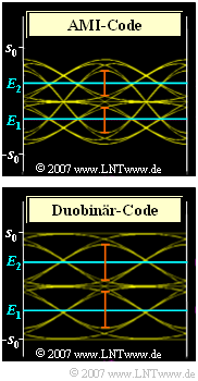
Exercise 3.5: Eye Opening with Pseudoternary Coding
Three digital transmission systems are considered, each with the following matching properties:
- NRZ rectangular pulses with amplitude $s_0 = 2 \, {\rm V}$,
- coaxial cable with characteristic cable attenuation $a_* = 40 \, {\rm dB}$,
- AWGN noise with noise power density $N_0$,
- receiver filter $H_{\rm E}(f) = 1/H_{\rm K}(f) \cdot H_{\rm G}(f) $ consisting of an ideal channel equalizer $H_{\rm K}(f)^{-1}$ and a Gaussian low-pass filter $H_{\rm G}(f)$ with normalized cutoff frequency $f_{\rm G} \cdot T \approx 0.5$,
- threshold decision with optimal decision thresholds and optimal detection time $T_{\rm D} = 0$.
The system variants to be investigated in the exercise differ only in terms of the line code:
⇒ $\text{System A}$ uses a binary bipolar redundancy-free transmission signal. The following descriptive variables are known:
- Basic detection pulse values $g_0 = 1.56 \, {\rm V}$, $g_1 = g_{\rm –1} = 0.22 \, {\rm V}$, $g_2 = g_{\rm –2} = \, \text{ ...} \, \approx 0$
- $$\Rightarrow \hspace{0.3cm}{\ddot{o}(T_{\rm D})}/{ 2} = g_{0} -g_{1}-g_{-1} = 1.12\,{\rm V} \hspace{0.05cm}.$$
- Noise rms value $\sigma_d \approx 0.2 \, {\rm V}$
- $$\Rightarrow \hspace{0.3cm}\rho_{\rm U} = \frac{\big[\ddot{o}(T_{\rm D})/2\big]^2}{ \sigma_d^2}\approx 31.36\,{\rm dB} \hspace{0.3cm}\Rightarrow \hspace{0.3cm} 10 \cdot {\rm lg}\hspace{0.1cm}\rho_{\rm U} \approx 15\,{\rm dB}\hspace{0.05cm}.$$
⇒ $\text{System B}$ uses AMI coding:
- Here the outer symbols $"+1"$ or $"–1"$ occur only in isolation.
- In the case of three consecutive symbols, the sequences "$\hspace{-0.1cm}\text{ ...} \, , \, +1, \, +1, \, +1, \,\text{ ...}$" and "$\hspace{-0.1cm}\text{ ...} \, , \, +1, \, 0, \, +1, \, \text{ ...} $" among others, are not possible,
- in contrast to the sequence "$\hspace{-0.1cm}\text{ ...} \, , \, +1, \, –1, \, +1, \, \text{ ...} $".
⇒ $\text{System C}$ uses the duobinary code:
- Here the alternating sequence "$\hspace{-0.1cm} \text{ ...} \, , \, –1, \, +1, \, –1, \, \text{ ...} $" is excluded by the code, which has a favorable effect on the eye opening.
Notes:
- The exercise belongs to the chapter "Intersymbol Interference for Multi-Level Transmission".
- Not all of the numerical values given here are necessary to solve this exercise.
Questions
Solution
- $$g_0 = 1.56 \, {\rm V}, \ g_1 = g_{\rm –1} = 0.22 \, {\rm V}, \ g_2 = g_{\rm –2} \approx 0.$$
In pseudo-ternary coding, there are always two eye openings:
- The upper boundary line of the upper eye results in the AMI code as in the redundancy-free binary system:
- $$d_{\rm top}= g_0 - 2 \cdot g_1 \hspace{0.2cm}\text{(associated sequence: } "\hspace{-0.1cm}-1, +1, -1\hspace{-0.1cm}") \hspace{0.05cm}.$$
- In contrast, for the lower boundary line of the upper eye:
- $$d_{\rm bottom}= g_1 \hspace{0.2cm}\text{(associated sequences: }\ "\hspace{-0.1cm}0,\ 0, +1\hspace{-0.1cm}"\hspace{0.2cm}\text{ and } "\hspace{-0.1cm}+1,\ 0,\ 0\hspace{-0.1cm}")\hspace{0.05cm}.$$
Thus, for the half eye opening, the following holds true:
- $${\ddot{o}(T_{\rm D})}/{2}= {1}/{2} \cdot (d_{\rm top} - d_{\rm bottom}) = {1}/{2} \cdot g_0 - {3}/{2} \cdot g_1 \hspace{0.15cm}\underline {= 0.45\,{\rm V}}\hspace{0.05cm}.$$
The corresponding equation for the redundancy-free binary system is:
- $${\ddot{o}(T_{\rm D})}/{2}= g_0 - 2 \cdot g_1 \hspace{0.05cm}.$$
(2) In terms of noise, there is no difference between the three systems since the same symbol rate is always present. It follows for the AMI code:
- $$\rho_{\rm U} = \frac{(0.45\,{\rm V})^2}{(0.2\,{\rm V})^2} = 5.06 \hspace{0.3cm}\Rightarrow \hspace{0.3cm} 10 \cdot {\rm lg}\hspace{0.1cm}\rho_{\rm U} \hspace{0.15cm}\underline {\approx 7\,{\rm dB}} \hspace{0.05cm}.$$
- The loss compared to the redundancy-free binary system is thus almost $8 \, {\rm dB}$.
- The reason for this serious loss of signal-to-noise ratio is that with the AMI code, despite $37\%$ redundancy, the symbol sequence "$\text{ ...} , \, –1, \, +1, \, –1, \text{ ...} $" is not excluded, which is particularly unfavorable with respect to intersymbol interference.
(3) The threshold $E_2$ must be in the middle between $d_{\rm top}$ and $d_{\rm bottom}$:
- $$E_2= {1}/{2} \cdot (d_{\rm top} + d_{\rm bottom}) = {1}/{2} \cdot (g_0 - g_1 ) \hspace{0.15cm}\underline {= 0.67\,{\rm V}}\hspace{0.05cm}.$$
- The threshold value $E_1$ is symmetrical to this: $E_1 \, \underline {= \, –0.67 {\rm V}}$.
(4) We again assume the same basic detection pulse values.
- The worst-case sequence with respect to the upper boundary line of the upper eye is "$\text{ ...} , 0, \, +1, \, 0, \text{ ...} $",
- while the lower boundary line is defined by "$\text{ ...} , 0, \, 0, \, +1, \text{ ...} $" or "$\text{ ...} , +1, \, 0, \, 0, \text{ ...} $" respectively.
- From this follows:
- $$d_{\rm top}= g_0, \hspace{0.2cm} d_{\rm bottom} = g_1 \hspace{0.3cm}\Rightarrow \hspace{0.3cm}{\ddot{o}(T_{\rm D})}/{2} = {g_0}/{2} - {g_1}/{2}\hspace{0.15cm}\underline { = 0.667\,{\rm V}} \hspace{0.05cm}.$$
(5) Using the result from (4), we obtain analogous to subtask (2):
- $$\rho_{\rm U} = \frac{(0.67\,{\rm V})^2}{(0.2\,{\rm V})^2} = 11.2 \hspace{0.3cm}\Rightarrow \hspace{0.3cm} 10 \cdot {\rm lg}\hspace{0.1cm}\rho_{\rm U} \hspace{0.15cm}\underline {\approx 10.5\,{\rm dB}} \hspace{0.05cm}.$$
- Prerequisite for this result are thresholds at
- $$E_2= {1}/{2} \cdot (g_0 + g_1 ) = 0.89\,{\rm V}, \hspace{0.2cm}E_1 = - 0.89\,{\rm V}\hspace{0.05cm}.$$
- It should be noted that the same cutoff frequency $f_{\rm G} \cdot T = 0.5$ was always assumed here.
- If the cutoff frequency is optimized, it may well be that the duobinary code is superior to the redundancy-free binary code if the characteristic cable attenuation is sufficiently large.
