Contents
Block diagram and requirements
We start from the block diagram already shown in the chapter Channel Models and Decision Structures where the channel model used is mostly the Binary Symmetric Channel (BSC). For codeword estimation, we use the Maximum Likelihood Decider (ML), which for binary codes ⇒ $\underline{x} \in {\rm GF}(2^n)$ at the block level gives the same result as the MAP Receiver.
The task of the channel decoder can be described as follows:
- The vector $\underline{v}$ after decoding (at the sink) should match the information word $\underline{u}$ as well as possible.
That is: The block error probability should be as small as possible:
- \[{ \rm Pr(block\:error)} = { \rm Pr}( \underline{v} \ne \underline{u}) \stackrel{!}{=} { \rm minimum}\hspace{0.05cm}.\]
- Because of deterministic assignments $\underline{x} = {\rm enc}(\underline{u})$ respectively, $\underline{v} = {\rm enc}^{-1}(\underline{z})$ but also holds:
- \[{ \rm Pr(block\:error)} = { \rm Pr}( \underline{z} \ne \underline{x}) \stackrel{!}{=} { \rm minimum}\hspace{0.05cm}.\]
- Sought thus is the most likely sent codeword $\underline{y} = \underline{x} +\underline{e}$ for the given received word $\underline{x}_i$, which is passed on as result $\underline{z}$ :
- \[\underline{z} = {\rm arg} \max_{\underline{x}_{\hspace{0.03cm}i} \hspace{0.05cm} \in \hspace{0.05cm} \mathcal{C}} \hspace{0.1cm} {\rm Pr}( \underline{x}_{\hspace{0.03cm}i} \hspace{0.05cm}|\hspace{0.05cm} \underline{y} ) \hspace{0.05cm}.\]
- For the BSC–channel, both $\underline{x}_i \in {\rm GF}(2^n)$ and $\underline{y} \in {\rm GF}(2^n)$, so the maximum–likelihood–rule can also be written using the Hamming distance $d_{\rm H}( \underline{y}, \, \underline{x}_i)$ :
- \[\underline{z} = {\rm arg} \min_{\underline{x}_{\hspace{0.03cm}i} \hspace{0.05cm} \in \hspace{0.05cm} \mathcal{C}} \hspace{0.1cm} d_{\rm H}(\underline{y} \hspace{0.05cm}, \hspace{0.1cm}\underline{x}_{\hspace{0.03cm}i})\hspace{0.05cm}.\]
Principle of syndrome decoding
Assumed here is a $(n, \, k)$–block code with the parity-check matrix $\boldsymbol{\rm H}$ and the systematic code words
- \[\underline{x}\hspace{0.05cm} = (x_1, x_2, \hspace{0.05cm}\text{...} \hspace{0.05cm}, x_i, \hspace{0.05cm}\text{...} \hspace{0.05cm}, x_n) = (u_1, u_2, \hspace{0.05cm}\text{...} \hspace{0.05cm}, u_k, p_1, \hspace{0.05cm}\text{...} \hspace{0.05cm}, p_{n-k})\hspace{0.05cm}. \]
Assumed here is a $(n, \, k)$–block code with the parity-check matrix $\boldsymbol{\rm H}$ and the systematic code words
- \[\underline{y} = \underline{x} + \underline{e} \hspace{0.05cm}, \hspace{0.4cm} \underline{y} \in \hspace{0.1cm} {\rm GF}(2^n) \hspace{0.05cm}, \hspace{0.4cm} \underline{x} \in \hspace{0.1cm} {\rm GF}(2^n) \hspace{0.05cm}, \hspace{0.4cm} \underline{e} \in \hspace{0.1cm} {\rm GF}(2^n) \hspace{0.05cm}.\]
A bit error at position $i$, that is $y_i ≠ x_i$, is expressed by the error coefficient $e_i = 1$.
$\text{Definition:}$ The syndrome $\underline{s} = (s_0, s_1, \hspace{0.05cm}\text{...} \hspace{0.05cm}, s_{m-1})$ is calculated (as a row– resp. column vector) from the receive word $\underline{y}$ and the parity-check matrix $\boldsymbol{\rm H}$ as follows:
- \[\underline{s} = \underline{y} \cdot { \boldsymbol{\rm H} }^{\rm T}\hspace{0.3cm}{\rm bzw.}\hspace{0.3cm} \underline{s}^{\rm T} = { \boldsymbol{\rm H} } \cdot \underline{y}^{\rm T}\hspace{0.05cm}.\]
The vector length of $\underline{s}$ is equal to $m = n-k$ $($row number of $\boldsymbol{\rm H})$.
The syndrome $\underline{s}$ shows the following characteristics:
- Because of the equation $\underline{x} \cdot { \boldsymbol{\rm H}}^{\rm T} = \underline{0}$ the syndrome $\underline{s}$ does not depend on the codeword $\underline{x}$ but solely on the error vector $\underline{e}$:
- \[\underline{s} = \underline{y} \cdot { \boldsymbol{\rm H}}^{\rm T} = \hspace{0.05cm} \underline{x} \cdot { \boldsymbol{\rm H}}^{\rm T} + \hspace{0.05cm} \underline{e} \cdot { \boldsymbol{\rm H}}^{\rm T} = \hspace{0.05cm} \underline{e} \cdot { \boldsymbol{\rm H}}^{\rm T} \hspace{0.05cm}.\]
- For sufficiently few bit errors, $\underline{s}$ provides a clear indication of the error locations, allowing full error correction.
$\text{Example 1:}$ Starting from the systematic $\text{(7, 4, 3)}$ Hamming code, the following result is obtained for the receive vector $\underline{y} = (0, 1, 1, 0, 0, 1)$ :
- \[{ \boldsymbol{\rm H} } \cdot \underline{y}^{\rm T} = \begin{pmatrix} 1 &1 &1 &0 &1 &0 &0\\ 0 &1 &1 &1 &0 &1 &0\\ 1 &1 &0 &1 &0 &0 &1 \end{pmatrix} \cdot \begin{pmatrix} 0 \\ 1 \\ 1 \\ 1 \\ 0 \\ 0 \\ 1 \end{pmatrix} = \begin{pmatrix} 0 \\ 1 \\ 1 \end{pmatrix} = \underline{s}^{\rm T} \hspace{0.05cm}.\]
Comparing the syndrome with the parity-check equations of the Hamming code, we see that
- most likely the fourth symbol $(x_4 = u_4)$ of the codeword has been corrupted,
- the codeword estimator will thus yield the result $\underline{z} = (0, 1, 1, 0, 0, 1)$ ,
- the decision is correct only if only one bit was corrupted during transmission.
Below are the required corrections for the $\text{(7, 4, 3)}$ Hamming code resulting from the calculated syndrome $\underline{s}$ corresponding to the columns of the parity-check matrix:
- \[\underline{s} = (0, 0, 0) \hspace{0.10cm} \Rightarrow\hspace{0.10cm}{\rm keine\hspace{0.15cm} Korrektur}\hspace{0.05cm};\hspace{0.8cm}\underline{s} = (1, 0, 0)\hspace{0.10cm} \Rightarrow\hspace{0.10cm}p_1{\rm \hspace{0.15cm} invertieren}\hspace{0.05cm};\]
- \[\underline{s} =(0, 0, 1)\hspace{0.10cm} \Rightarrow\hspace{0.10cm} p_3{\rm \hspace{0.15cm} invertieren}\hspace{0.05cm};\hspace{1.22cm}\underline{s} = (1, 0, 1)\hspace{0.10cm} \Rightarrow\hspace{0.10cm} u_1{\rm \hspace{0.15cm} invertieren}\hspace{0.05cm};\]
- \[\underline{s} =(0, 1, 0)\hspace{0.10cm} \Rightarrow\hspace{0.10cm} p_2{\rm \hspace{0.15cm} invertieren}\hspace{0.05cm};\hspace{1.22cm}\underline{s} = (1, 1, 0)\hspace{0.10cm} \Rightarrow\hspace{0.10cm} u_3{\rm \hspace{0.15cm} invertieren}\hspace{0.05cm};\]
- \[\underline{s} =(0, 1, 1)\hspace{0.10cm} \Rightarrow\hspace{0.10cm} u_4{\rm \hspace{0.15cm} invertieren}\hspace{0.05cm};\hspace{1.22cm}\underline{s} = (1, 1, 1)\hspace{0.10cm} \Rightarrow\hspace{0.10cm} u_2{\rm \hspace{0.15cm} invertieren}\hspace{0.05cm}. \]
Generalization of syndrome coding
We continue to assume the BSC channel model. This means:
- The receive vector $\underline{y}$ and the error vector $\underline{e}$ are elements of ${\rm GF}(2^n)$.
- The possible codewords $\underline{x}_i$ belong to the code $\mathcal{C}$, which spans a $(n-k)$ dimensional subspace of ${\rm GF}(2^n)$ .
Under this assumption, we briefly summarize again the results of the last pages:
- Syndrome decoding is a realization possibility of maximum likelihood detection of block codes. One decides on the codeword $\underline{x}_i$ with the least Hamming distance to the receiving word $\underline{y}$ :
- \[\underline{z} = {\rm arg} \min_{\underline{x}_{\hspace{0.03cm}i} \hspace{0.05cm} \in \hspace{0.05cm} \mathcal{C}} \hspace{0.1cm} d_{\rm H}(\underline{y} \hspace{0.05cm}, \hspace{0.1cm}\underline{x}_{\hspace{0.03cm}i})\hspace{0.05cm}.\]
- But the syndrome decoding is also the search for the most probable error vector $\underline{e}$ that satisfies the condition $\underline{e} \cdot { \boldsymbol{\rm H}}^{\rm T} = \underline{s}$ . The syndrome is thereby determined by the equation $\underline{s} = \underline{y} \cdot { \boldsymbol{\rm H}}^{\rm T} $ .
- With the Hamming weight $w_{\rm H}(\underline{e})$ the second interpretation can also be mathematically formulated as follows:
- \[\underline{z} = \underline{y} + {\rm arg} \min_{\underline{e}_{\hspace{0.03cm}i} \hspace{0.05cm} \in \hspace{0.05cm} {\rm GF}(2^n)} \hspace{0.1cm} w_{\rm H}(\underline{e}_{\hspace{0.03cm}i})\hspace{0.05cm}.\]
$\text{Conclusion:}$ Note that the error vector $\underline{e}$ as well as the receive vector $\underline{y}$ is an element of ${\rm GF}(2^n)$ unlike the syndrome $\underline{s} \in {\rm GF}(2^m)$ with number $m = n-k$ of parity-check equations. This means,
- that the association between the syndrome $\underline{s}$ and the error vector $\underline{e}$ is not unique, but
- that each $2^k$ error vectors lead to the same syndrome $\underline{s}$ which one groups together into a coset
.
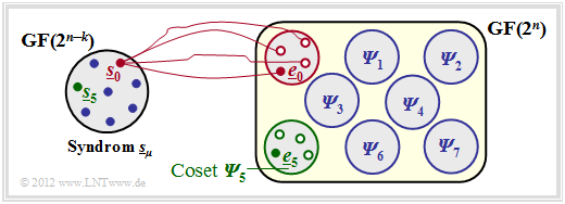
$\text{Example 2:}$ The facts shall be illustrated here by the example $n = 5, \ k = 2$ ⇒ $m = n-k = 3$ .
You can see from this graph:
- The $2^n = 32$ possible error vectors $\underline{e}$ are divided into $2^m = 8$ cosets ${\it \Psi}_0$, ... , ${\it \Psi}_7$ split.
- Explicitly drawn here are only the cosets ${\it \Psi}_0$ and ${\it \Psi}_5$.
- All $2^k = 4$ error vectors of the coset ${\it \Psi}_\mu$ lead to the syndrome $\underline{s}_\mu$.
- Each minor class ${\it \Psi}_\mu$ has a leader $\underline{e}_\mu$, namely the one with the minimum Hamming weight.
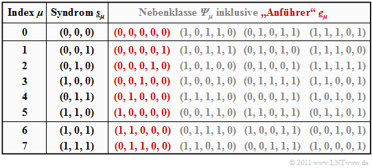
$\text{Example 3:}$ Starting from the systematic $\text{(5, 2, 3)}$ code $\mathcal{C} = \big \{ (0, 0, 0, 0, 0) \hspace{0.05cm},\hspace{0.15cm}(0, 1, 0, 1, 1) \hspace{0.05cm},\hspace{0.15cm}(1, 0, 1, 1, 0) \hspace{0.05cm},\hspace{0.15cm}(1, 1, 1, 0, 1) \big \}$ the syndrome decoding procedure is now described in detail.
The generator matrix and the parity-check matrix are:
- \[{ \boldsymbol{\rm G} } = \begin{pmatrix} 1 &0 &1 &1 &0 \\ 0 &1 &0 &1 &1 \end{pmatrix} \hspace{0.05cm},\]
- \[{ \boldsymbol{\rm H} } = \begin{pmatrix} 1 &0 &1 &0 &0 \\ 1 &1 &0 &1 &0 \\ 0 &1 &0 &0 &1 \end{pmatrix} \hspace{0.05cm}.\]
The table summarizes the final result. Note:
- The index $\mu$ is not identical to the binary value of $\underline{s}_\mu$.
- The order is rather given by the number of ones in the minor class leader $\underline{e}_\mu$.
- For example, the syndrome $\underline{s}_5 = (1, 1, 0)$ and the syndrome $\underline{s}_6 = (1, 0, 1)$.
To derive this table, note:
- The row 1 refers to the syndrome $\underline{s}_0 = (0, 0, 0)$ and the associated cosets ${\it \Psi}_0$. The most likely error sequence here is $(0, 0, 0, 0)$ ⇒ no bit error, which we call the coset leader $\underline{e}_0$ .
- The other entries in the first row, namely $(1, 0, 1, 1, 0 )$, $(0, 1, 0, 1, 1)$ and $(1, 1, 1, 0, 1 )$, each yield the syndrome $\underline{s}_0 = (0, 0, 0)$, but yield only with at least three bit errors and are correspondingly unlikely.
- In rows 2 to 6, the respective coset leader $\underline{e}_\mu$ contains exactly a single one $(\mu = 1$, ... , $5)$. Here $\underline{e}_\mu$ is always the most likely error pattern of the class ${\it \Psi}_\mu$. The other group members result only with at least two bit errors.
- The syndrome $\underline{s}_6 = (1, 0, 1)$ is not possible with only one bit error. In creating the table, we then considered all $5\text{ over }2 = 10$ error patterns $\underline{e}$ with weight $w_{\rm H}(\underline{e}) = 2$ .
- The first found sequence with syndrome $\underline{s}_6 = (1, 0, 1)$ was chosen as coset leader $\underline{e}_6 = (1, 1, 0, 0)$ . With a different probing order, the sequence $(0, 0, 1, 0, 1)$ could also have resulted from ${\it \Psi}_6$ .
- Similar procedure was followed in determining the leader $\underline{e}_7 = (0, 1, 1, 0, 0)$ of the cosets class ${\it \Psi}_7$ characterized by the uniform syndrome $\underline{s}_7 = (1, 1, 1)$ . Also in the class ${\it \Psi}_7$ there is another sequence with Hamming weight $w_{\rm H}(\underline{e}) = 2$, namely $(1, 0, 0, 0, 1)$.
The above table only needs to be created once and can be used as often as desired. First, the syndrome must be determined. This is for example for the receive vector $\underline{y} = (0, 1, 0, 0, 1)$:
- \[\underline{s} = \underline{y} \cdot { \boldsymbol{\rm H} }^{\rm T} = \begin{pmatrix} 0 &1 &0 &0 &1 \end{pmatrix} \cdot \begin{pmatrix} 1 &1 &0 \\ 0 &1 &1 \\ 1 &0 &0 \\ 0 &1 &0 \\ 0 &0 &1 \\ \end{pmatrix} = \begin{pmatrix} 0 &1 &0 \end{pmatrix}= \underline{s}_2 \hspace{0.05cm}.\]
Using the coset leader $\underline{e}_2 = (0, 0, 0, 1, 0)$ from the above table $($red entry for $\mu =2)$ finally arrives at the decoding result:
- \[\underline{z} = \underline{y} + \underline{e}_2 = (0,\hspace{0.05cm} 1,\hspace{0.05cm} 0,\hspace{0.05cm} 0,\hspace{0.05cm} 1) + (0,\hspace{0.05cm} 0,\hspace{0.05cm} 0,\hspace{0.05cm} 1,\hspace{0.05cm} 0) = (0,\hspace{0.05cm} 1,\hspace{0.05cm} 0,\hspace{0.05cm} 1,\hspace{0.05cm} 1) \hspace{0.05cm}.\]
$\text{Conclusion:}$ From these examples it is already clear that the syndrome decoding involves a considerable effort is connected, if one cannot use certain characteristics as with cyclic codes:
- For large block code lengths, this method fails completely. Thus, to decode a BCH codes – the abbreviation stands for their inventors Bose, Chaudhuri and Hocquenghem – with code parameters $n = 511$, $k = 259$ and $d_{\rm min} = 61$ exactly $2^{511-259} \approx 10^{76}$ evaluate and save error patterns of length $511$ .
- Happily, however, there are special decoding algorithms for these and also for other codes of large block length, which lead to success with less effort
.
Codiergewinn – Bitfehlerrate bei AWGN
Wir betrachten nun die Bitfehlerquote (oder Bitfehlerrate, englisch: Bit Error Rate , BER) für folgende Konstellation:
- Hamming–Code $\text{HC (7, 4, 3)}$,
EN_KC_T_1_5_S3b_neu.png
- AWGN–Kanal, gekennzeichnet durch den Quotienten $E_{\rm B}/N_0$ (in dB),
- Maximum–Likelihood–Detektion (ML) mit Hard Decision bzw. Soft Decision.
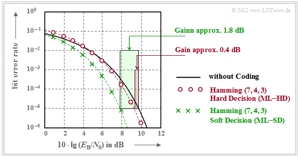
Zu dieser Grafik ist anzumerken:
- Die schwarze Vergleichskurve gilt beispielsweise für die binäre Phasenmodulation (BPSK) ohne Codierung. Hierfür benötigt man für die Bitfehlerrate $10^{-5}$ etwa $10 \cdot \lg \, E_{\rm B}/N_0 = 9.6 \, \rm dB$.
- Die roten Kreise gelten für den $\text{(7, 4, 3)}$–Code und harte Entscheidungen des Maximum–Likelihood–Decoders $\text{(ML–HD)}$. Die Syndromdecodierung ist hierfür eine mögliche Realisierungsform.
- Diese Konfiguration bringt erst für $10 \cdot \lg \, E_{\rm B}/N_0 >6 \, \rm dB$ eine Verbesserung gegenüber dem Vergleichssystem. Für $\rm BER =10^{-5}$ benötigt man nur noch $10 \cdot \lg \, E_{\rm B}/N_0 \approx 9.2 \, \rm dB$.
- Die grünen Kreuze für den Hamming–Code und Soft–Decision $\text{(ML–SD)}$ liegen im gesamten Bereich unterhalb der Vergleichskurve. Für $\rm BER =10^{-5}$ ergibt sich $10 \cdot \lg \, E_{\rm B}/N_0 \approx 7.8 \, \rm dB$.
$\text{Definition:}$ Als Codiergewinn einer Systemkonfiguration (gekennzeichnet durch seinen Code und die Art der Decodierung) bezeichnen wir das gegenüber dem Vergleichssystem (ohne Codierung) kleinere $10 \cdot \lg \, E_{\rm B}/N_0$, das für eine vorgegebene Bitfehlerrate $\rm (BER)$ erforderlich ist:
- \[G_{\rm Code} (\hspace{0.05cm}{\rm System}\hspace{0.05cm}\vert\hspace{0.05cm}{\rm BER}\hspace{0.05cm}) =10 \cdot {\rm lg}\hspace{0.1cm}{E}_{\rm B}/N_0 \hspace{0.15cm}(\hspace{0.05cm}{\rm ohne\hspace{0.1cm} Codierung}\hspace{0.05cm}\vert\hspace{0.05cm}{\rm BER}\hspace{0.05cm})- 10 \cdot {\rm lg}\hspace{0.1cm}{E}_{\rm B}/N_0 \hspace{0.15cm}(\hspace{0.05cm}{\rm System}\hspace{0.05cm}\vert\hspace{0.05cm}{\rm BER}\hspace{0.05cm}) \hspace{0.05cm}. \]
Angewendet auf die obige Grafik erhält man:
\[G_{\rm Code} (\hspace{0.05cm}{\rm Hamming \hspace{0.1cm}(7,\hspace{0.02cm}4,\hspace{0.02cm}3), ML-HD}\hspace{0.05cm}|\hspace{0.05cm}{\rm BER} = 10^{-5}\hspace{0.05cm}) = 0.4\ {\rm dB}\hspace{0.05cm},\]
\[G_{\rm Code} (\hspace{0.05cm}{\rm Hamming \hspace{0.1cm}(7,\hspace{0.02cm}4,\hspace{0.02cm}3), ML-SD}\hspace{0.05cm}|\hspace{0.05cm}{\rm BER} = 10^{-5}\hspace{0.05cm}) = 1.8\ {\rm dB}\hspace{0.05cm}.\]
Decodierung beim Binary Erasure Channel
Abschließend soll noch gezeigt werden, in wie weit der Decoder zu modifizieren ist, wenn anstelle des BSC–Modells (Binary Symmetric Channel ) das BEC–Kanalmodell (Binary Erasure Channel ) zum Einsatz kommt, der keine Fehler produziert, sondern unsichere Bit als Auslöschungen markiert.
$\text{Beispiel 4:}$ Ohne Einschränkung der Allgemeingültigkeit betrachten wir wie im $\text{Beispiel 3}$ wieder den systematischen $\text{(5, 2, 3)}$–Blockcode
- $$\mathcal{C} = \big \{ (0, 0, 0, 0, 0) \hspace{0.05cm},\hspace{0.15cm}(0, 1, 0, 1, 1) \hspace{0.05cm},\hspace{0.15cm}(1, 0, 1, 1, 0) \hspace{0.05cm},\hspace{0.15cm}(1, 1, 1, 0, 1) \big \}.$$
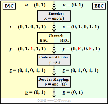
Die Grafik zeigt das Systemmodell und gibt beispielhafte Werte für die einzelnen Vektoren wider.
- Der linke Bildteil (gelb hinterlegt) gilt für "BSC" mit einem Bitfehler $0 → 1$ beim dritten Bit.
- Der rechte Bildteil (grün hinterlegt) gilt für "BEC" und zeigt zwei Erasures $\rm 1 → E$ bei Bit 2 und Bit 4.
Man erkennt:
- Bei BSC kann wegen $d_{\rm min} = 3$ nur ein Bitfehler korrigiert werden ($t = 1$, rot markiert). Beschränkt man sich auf Fehlererkennung, so funktioniert diese bis zu $e= d_{\rm min} -1 = 2$ Bitfehler.
- Bei BEC macht Fehlererkennung keinen Sinn, denn bereits der Kanal lokalisiert ein unsicheres Bit als Erasure $\rm E$ (Auslöschung). Die Nullen und Einsen im BEC–Empfangswort $\underline{y}$ sind sicher. Deshalb funktioniert hier die Fehlerkorrektur bis zu $e = 2$ Auslöschungen mit Sicherheit.
- Auch $e = 3$ Auslöschungen sind manchmal noch korrigierbar. So kann $\underline{y} \rm = (E, E, E, 1, 1)$ zu $\underline{z} \rm = (0, 1, 0, 1, 1)$ korrigiert werden, da kein zweites Codewort mit zwei Einsen endet. $\underline{y} \rm = (0, E, 0, E, E)$ ist aber aufgrund des im Code erlaubten Nullwortes nicht korrigierbar.
- Wird sichergestellt, dass in keinem Empfangswort mehr als zwei Auslöschungen vorkommen, so ist die BEC–Blockfehlerwahrscheinlichkeit ${\rm Pr}(\underline{z} \ne \underline{x}) = {\rm Pr}(\underline{v} \ne \underline{u}) \equiv 0$. Dagegen hat die entsprechende Blockfehlerwahrscheinlichkeit beim BSC–Modell stets einen Wert größer als $0$.
Da nach dem BEC ein jedes Empfangswort entweder richtig oder gar nicht decodiert wird, nennen wir hier den Block $\underline{y} → \underline{z}$ zukünftig "Codewortfinder". Eine "Schätzung" findet nur beim BSC–Modell statt.
Wie funktioniert aber nun die Decodierung eines Empfangswortes $\underline{y}$ mit Auslöschungen algorithmisch?
$\text{Beispiel 5:}$ Ausgehend vom Empfangswort $\underline{y} \rm = (0, E, 0, E, 1)$ im $\text{Beispiel 4}$ setzen wir den Ausgang des Codewortfinders formal zu $\underline{z} \rm = (0, z_2, 0, z_4, 1)$, wobei die Symbole $z_2 \in \{0, \, 1\}$ und $z_4 \in \{0, \, 1\}$ entsprechend folgender Gleichung zu bestimmen sind:
- \[\underline{z} \cdot { \boldsymbol{\rm H} }^{\rm T}= \underline{0} \hspace{0.3cm} \Rightarrow \hspace{0.3cm} { \boldsymbol{\rm H} } \cdot \underline{z}^{\rm T}= \underline{0}^{\rm T} \hspace{0.05cm}.\]
Es geht nun darum, diese Bestimmungsgleichung möglichst effizient umzusetzen. Es ergeben sich folgende Rechenschritte:
- Mit der Prüfmatrix $\boldsymbol{\rm H}$ des $\text{(5, 2, 3)}$–Blockcodes und dem Vektor $\underline{z} \rm = (0, z_2, 0, z_4, 1)$ lautet die obige Bestimmungsgleichung:
- \[{ \boldsymbol{\rm H} } \cdot \underline{z}^{\rm T} = \begin{pmatrix} 1 &0 &1 &0 &0\\ 1 &1 &0 &1 &0\\ 0 &1 &0 &0 &1 \end{pmatrix} \cdot \begin{pmatrix} 0 \\ z_2 \\ 0 \\ z_4 \\ 1 \end{pmatrix} = \begin{pmatrix} 0 \\ 0 \\ 0 \end{pmatrix} \hspace{0.05cm}.\]
- Wir fassen die sicheren (korrekten) Bit zum Vektor $\underline{z}_{\rm K}$ zusammen und die ausgelöschten Bit zum Vektor $\underline{z}_{\rm E}$. Dann teilen wir die Prüfmatrix $\boldsymbol{\rm H}$ in die entsprechenden Teilmatrizen $\boldsymbol{\rm H}_{\rm K}$ und $\boldsymbol{\rm H}_{\rm E}$ auf:
- \[\underline{z}_{\rm K} =(0, 0, 1)\hspace{0.05cm},\hspace{0.3cm} { \boldsymbol{\rm H} }_{\rm K}= \begin{pmatrix} 1 &1 &0\\ 1 &0 &0\\ 0 &0 &1 \end{pmatrix} \hspace{0.3cm}\Rightarrow\hspace{0.3cm} {\rm Spalten\hspace{0.15cm} 1,\hspace{0.15cm}3 \hspace{0.15cm}und \hspace{0.15cm}5 \hspace{0.15cm}der \hspace{0.15cm}Pr\ddot{u}fmatrix} \hspace{0.05cm},\]
- \[\underline{z}_{\rm E} = (z_2, z_4)\hspace{0.05cm},\hspace{0.35cm} { \boldsymbol{\rm H} }_{\rm E}= \begin{pmatrix} 0 &0\\ 1 &1\\ 1 &0 \end{pmatrix} \hspace{0.9cm}\Rightarrow\hspace{0.3cm} {\rm Spalten\hspace{0.15cm} 2 \hspace{0.15cm}und \hspace{0.15cm}4 \hspace{0.15cm}der \hspace{0.15cm}Pr\ddot{u}fmatrix} \hspace{0.05cm}.\]
- Unter Berücksichtigung der Tatsache, dass in $\rm GF(2)$ die Subtraktion gleich der Addition ist, lässt sich die obige Gleichung wie folgt darstellen:
- \[{ \boldsymbol{\rm H} }_{\rm K} \cdot \underline{z}_{\rm K}^{\rm T} + { \boldsymbol{\rm H} }_{\rm E} \cdot \underline{z}_{\rm E}^{\rm T}= \underline{0}^{\rm T} \hspace{0.3cm} \Rightarrow \hspace{0.3cm} { \boldsymbol{\rm H} }_{\rm E} \cdot \underline{z}_{\rm E}^{\rm T}= { \boldsymbol{\rm H} }_{\rm K} \cdot \underline{z}_{\rm K}^{\rm T} \hspace{0.3cm} \Rightarrow \hspace{0.3cm} \begin{pmatrix} 0 &0\\ 1 &1\\ 1 &0 \end{pmatrix} \cdot \begin{pmatrix} z_2 \\ z_4 \end{pmatrix} = \begin{pmatrix} 1 &1 &0\\ 1 &0 &0\\ 0 &0 &1 \end{pmatrix} \cdot \begin{pmatrix} 0 \\ 0 \\ 1 \end{pmatrix} = \begin{pmatrix} 0 \\ 0 \\ 1 \end{pmatrix} \hspace{0.05cm}.\]
- Dies führt zu einem linearen Gleichungssystem mit zwei Gleichungen für die unbekannten $z_2$ und $z_4$ $($jeweils $0$ oder $1)$.
- Aus der letzten Zeile folgt $z_2 = 1$ und aus der zweiten Zeile $z_2 + z_4 = 0$ ⇒ $z_4 = 1$.
- Damit ergibt sich das zulässige Codewort $\underline{z} \rm = (0, 1, 0, 1, 1)$.
Aufgaben zum Kapitel
Aufgabe 1.11: Syndromdecodierung
Aufgabe 1.11Z: Nochmals Syndromdecodierung
Aufgabe 1.12: Hard Decision vs. Soft_Decision
Aufgabe 1.12Z: Vergleich von HC (7, 4, 3) und HC (8, 4, 4)
Aufgabe 1.13: Decodierung beim binären Auslöschungskanal (BEC)
Aufgabe 1.13Z: Nochmals BEC–Decodierung


