Difference between revisions of "Aufgaben:Exercise 1.5: HDB3 Coding"
| Line 5: | Line 5: | ||
[[File:EN_Bei_A_1_5.png|right|frame|Signals with HDB3 coding]] | [[File:EN_Bei_A_1_5.png|right|frame|Signals with HDB3 coding]] | ||
| − | The ISDN primary rate interface is based on the $\rm | + | The ISDN primary rate interface $\rm (PRI)$ is based on the $\rm PCM\ system \ 30/32$ and offers |
| + | *$30$ full-duplex basic channels, | ||
| − | + | *plus a signaling channel | |
| − | |||
| − | |||
| − | + | *and a synchronization channel. | |
| − | * | ||
| − | |||
| − | + | Each of these channels, which are transmitted in time division multiplex, has a data rate of $64 \ \rm kbit/s$. A frame consists of one byte $\rm (8$ bits$)$ of all $32$ channels. The duration of such a frame $($German: "Rahmen"$)$ is denoted by $T_{\rm R}$, while $T_{\rm B}$ indicates the bit duration. | |
| + | On both the $\rm S_{\rm 2M}$ and $\rm U_{\rm K2}$ interfaces of the ISDN system under consideration, the '''HDB3 code''' is used, which is derived from the AMI code. This is a pseudo-ternary code $($symbol set size $M = 3$, symbol duration $T = T_{\rm B})$, that differs from the AMI code in that long zero sequences are avoided by deliberately violating the AMI coding rule. The following applies: | ||
| + | If four consecutive "'''0'''" symbols occur in the AMI-encoded signal $a(t)$, these are replaced by four other ternary symbols: | ||
| + | *If an even number of "+'''1'''" occurred before this four-symbol block the signal $a(t)$ and the last pulse is positive, "'''0 0 0 0'''" is replaced by "– '''0 0''' –". If the last pulse is negative, "'''0 0 0 0'''" is replaced by "+ '''0 0''' +". | ||
| + | *On the other hand, if there is an odd number of "ones" before this "'''0 0 0 0'''" block, "'''0 0 0''' +" $($if last pulse positive$)$ or "'''0 0 0''' –" $($if last pulse negative$)$ are selected. | ||
| + | The graph above shows the binary signal $q(t)$ and the signal $a(t)$ after AMI coding. The HDB3 signal, which you are to determine in the course of this exercise, is denoted by $c(t)$. | ||
| − | + | ||
| + | |||
| + | |||
| + | Notes: | ||
*The exercise belongs to the chapter [[Examples_of_Communication_Systems/ISDN_Primary_Multiplex_Connection|"ISDN Primary Multiplex Connection"]] . | *The exercise belongs to the chapter [[Examples_of_Communication_Systems/ISDN_Primary_Multiplex_Connection|"ISDN Primary Multiplex Connection"]] . | ||
| − | *Information about the pseudo-ternary codes can be found in the [[Digital_Signal_Transmission/Symbolwise_Coding_with_Pseudo-Ternary_Codes|"Symbolwise Coding with Pseudo-Ternary Codes"]] of "Digital Signal Transmission". | + | *Information about the pseudo-ternary codes can be found in the section [[Digital_Signal_Transmission/Symbolwise_Coding_with_Pseudo-Ternary_Codes|"Symbolwise Coding with Pseudo-Ternary Codes"]] of "Digital Signal Transmission". |
Revision as of 10:24, 28 October 2022
The ISDN primary rate interface $\rm (PRI)$ is based on the $\rm PCM\ system \ 30/32$ and offers
- $30$ full-duplex basic channels,
- plus a signaling channel
- and a synchronization channel.
Each of these channels, which are transmitted in time division multiplex, has a data rate of $64 \ \rm kbit/s$. A frame consists of one byte $\rm (8$ bits$)$ of all $32$ channels. The duration of such a frame $($German: "Rahmen"$)$ is denoted by $T_{\rm R}$, while $T_{\rm B}$ indicates the bit duration.
On both the $\rm S_{\rm 2M}$ and $\rm U_{\rm K2}$ interfaces of the ISDN system under consideration, the HDB3 code is used, which is derived from the AMI code. This is a pseudo-ternary code $($symbol set size $M = 3$, symbol duration $T = T_{\rm B})$, that differs from the AMI code in that long zero sequences are avoided by deliberately violating the AMI coding rule. The following applies:
If four consecutive "0" symbols occur in the AMI-encoded signal $a(t)$, these are replaced by four other ternary symbols:
- If an even number of "+1" occurred before this four-symbol block the signal $a(t)$ and the last pulse is positive, "0 0 0 0" is replaced by "– 0 0 –". If the last pulse is negative, "0 0 0 0" is replaced by "+ 0 0 +".
- On the other hand, if there is an odd number of "ones" before this "0 0 0 0" block, "0 0 0 +" $($if last pulse positive$)$ or "0 0 0 –" $($if last pulse negative$)$ are selected.
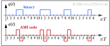
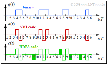
The graph above shows the binary signal $q(t)$ and the signal $a(t)$ after AMI coding. The HDB3 signal, which you are to determine in the course of this exercise, is denoted by $c(t)$.
Notes:
- The exercise belongs to the chapter "ISDN Primary Multiplex Connection" .
- Information about the pseudo-ternary codes can be found in the section "Symbolwise Coding with Pseudo-Ternary Codes" of "Digital Signal Transmission".
Questions
Solution
(1) The total data rate of the $32$ channels at $64 \ \rm kbit/s$ each results in
- $$R_{\rm B} \underline{ = 2.048 \ \rm Mbit/s}.$$
(2) The bit duration is $T_{\rm B} = 1/R_{\rm B} \underline{ = 0.488 \ \rm µ s}$.
- One byte (8 bits) of each channel is transmitted per frame. It follows that:
- $$T_{\rm R} = 32 \cdot 8 \cdot T_{\rm B} \hspace{0.15cm}\underline{= 125 \,{\rm µ s}}\hspace{0.05cm}.$$
(3) By time $t = 6T$, a "+1" has occurred exactly once in the AMI-encoded signal$a(t)$.
- Because of $a_{5} = –1$, in the HDB3 code "0 0 0 0" is replaced by (see diagram)
- $$\underline{c_{6} = 0, \hspace{0.2cm}c_{7} = 0, \hspace{0.2cm}c_{8} = 0, \hspace{0.2cm}c_{9} = -1} \hspace{0.05cm}.$$
- In contrast, $\underline{c_{10} = a_{10} = 0}$ is not changed by HDB3 coding.
(4) Up to and including $a_{13}$, there are three times a "+1" ⇒ odd number. Because of $a_{12} = +1$, this zero block is replaced as follows:
- $$ \underline{c_{14} = 0, \hspace{0.2cm}c_{15} = 0, \hspace{0.2cm}c_{16} = 0, \hspace{0.2cm}c_{17} = +1} \hspace{0.05cm}.$$
(5) In the AMI encoded signal, "+1" occurs exactly four times up to and including $a_{19}$ ⇒ even number.
- Because of $a_{19} = +1$, the substitution according to rule 2 in the information section is:
- $$\underline{c_{20} = -1, \hspace{0.2cm}c_{21} = 0, \hspace{0.2cm}c_{22} = 0, \hspace{0.2cm}c_{23} = -1} \hspace{0.05cm}.$$
- The zero symbol $a_{24}$ remains unchanged: $\underline{c_{24} = 0}$.

