Exercise 3.10Z: Amplitude and Angle Modulation in Comparison
Consider the transmission of a cosine signal with amplitude modulation $\rm (AM)$ and angle modulation $\rm (WM)$. The following boundary conditions apply::
- Message frequency $f_{\rm N} = 10 \ \rm kHz$,
- Transmission power $P_{\rm S} = 100 \ \rm kW$,
- Channel transmission factor $20 · \lg α_{\rm K} = -120 \ \rm dB$,
- noise power density $N_0 = 10^{–16} \ \rm W/Hz$.
These system parameters are conveniently combined to form the performance parameter:
$$ \xi = \frac{\alpha_{\rm K}^2 \cdot P_{\rm S}}{N_0 \cdot B_{\rm NF}}$$
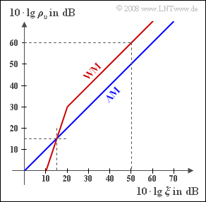
The graph shows the resulting sink-to-noise ratio $10 · \lg ρ_v$ as a function of the logarithmized performance parameter $ξ$.
Hints:
- This exercise belongs to the chapter Modulation Methods/Influence of Noise on Systems with Angle Modulation.
- Reference is also made to the page Sink SNR and the performance parameter and the chapter Frequency Modulation.
- The following relationships hold:
- $$\rho_{v } = \left\{ \begin{array}{c} \xi \\ {\eta^2}/2 \cdot\xi \\ 3{\eta^2}/2 \cdot\xi \\ \end{array} \right.\quad \begin{array}{*{10}c} {\rm{for}} \\ {\rm{for}} \\ {\rm{for}} \\ \end{array}\begin{array}{*{20}l} {\rm DSB/SSB-AM \hspace{0.15cm}without \hspace{0.15cm}carrier} \hspace{0.05cm}, \\ {\rm PM \hspace{0.15cm}with \hspace{0.15cm}modulation\hspace{0.15cm}depth \hspace{0.15cm} \eta } \hspace{0.05cm}, \\ {\rm FM \hspace{0.15cm}with \hspace{0.15cm}modulation\hspace{0.15cm}depth \hspace{0.15cm} \eta }\hspace{0.05cm}. \\ \end{array}$$
- The bandwidths $B_{\rm K}$ for angle modulation shall be selected according to the "Carson rule" to guarantee a distortion factor of $K < 1\%$ :
- $$ B_{\rm K} = 2 \cdot f_{\rm N} \cdot (\eta +2) \hspace{0.05cm}.$$
Questions
Solution
- $$ \xi = \frac{\alpha_{\rm K}^2 \cdot P_{\rm S}}{N_0 \cdot B_{\rm NF}}= \frac{10^{-12} \cdot 10^{5}\;{\rm W}}{10^{-16}\;{\rm W/Hz} \cdot 10^{4}\;{\rm Hz}}= 10^5 \hspace{0.3cm}\Rightarrow \hspace{0.3cm}10 \cdot {\rm lg} \hspace{0.15cm}\xi \hspace{0.15cm}\underline {= 50\,{\rm dB}}\hspace{0.05cm}.$$
(2) Aus der Grafik ist zu entnehmen, dass beim AM–System $ρ_v = ξ$ gilt. Damit ergibt sich für den Sinken-Störabstand:
- $$10 \cdot {\rm lg} \hspace{0.15cm}\rho_{v }\hspace{0.15cm}\underline {= 50\,{\rm dB}}\hspace{0.05cm}.$$
(3) Richtig sind die ersten drei Lösungsvorschläge:
- Es handelt sich um eine ZSB–AM oder eine ESB–AM, jeweils ohne Träger.
- Dagegen scheiden die ZSB–AM und die ESB–AM mit Träger aus. In diesen Fällen würde stets $ρ_v < \xi$ sein.
(4) Bei der ZSB–AM muss $B_{\rm K} ≥ 2 · f_{\rm N}\hspace{0.15cm}\underline { = 20 \ \rm kHz}$ gelten.
(5) Aus der angegebenen Grafik erkennt man, dass ab etwa $20 \ \rm dB$ gilt:
- $$10 \cdot {\rm lg} \hspace{0.15cm}\rho_{v }= 10 \cdot {\rm lg} \hspace{0.15cm}\xi + 10\,{\rm dB}. \hspace{0.3cm}{\rm Mit}\hspace{0.15cm}10 \cdot {\rm lg} \hspace{0.15cm}\xi = 50\,{\rm dB}\hspace{0.05cm}\hspace{0.3cm}\Rightarrow \hspace{0.3cm}10 \cdot {\rm lg} \hspace{0.15cm}\rho_{v }\hspace{0.15cm}\underline {= 60\,{\rm dB}}.$$
(6) Bei Phasenmodulation gilt:
- $$ \rho_{v }= \frac{\eta^2}{2} \cdot \xi \hspace{0.3cm}\Rightarrow \hspace{0.3cm} \eta^2 = \frac{2 \cdot \rho_{v }}{\xi} = 20\hspace{0.3cm}\Rightarrow \hspace{0.3cm} \eta \approx 4.47 \hspace{0.05cm}.$$
- Damit muss für die Kanalbandbreite unter der Voraussetzung $K < 1\%$ gelten:
- $$B_{\rm K} \ge 2 \cdot f_{\rm N} \cdot (\eta +2) = 20\,{\rm kHz}\cdot 6.47 \hspace{0.15cm}\underline { \approx 130\,{\rm kHz}}\hspace{0.05cm}.$$
(7) Hier genügt ein kleinerer Modulationsindex und damit auch eine kleinere Bandbreite:
- $${3}/{2}\cdot \eta^2 = 10\hspace{0.3cm}\Rightarrow \hspace{0.3cm} \eta \approx 2.58 \hspace{0.3cm}\Rightarrow \hspace{0.3cm}B_{\rm K} = 20\,{\rm kHz}\cdot 4.58 \hspace{0.15cm}\underline {\approx 91.6\,{\rm kHz}}\hspace{0.05cm}.$$
(8) In der Grafik erkennt man den so genannten FM–Knick.
- Für $10 · \lg \hspace{0.08cm} ξ = 15 \ \rm dB$ erhält man für das WM–System genau das gleiche Sinken–SNR wie für das AM–System.
- Die Sendeleistung kann also um $35 \ \rm dB$ kleiner sein als $100 \ \rm kW$:
- $$ 10 \cdot {\rm lg} \hspace{0.15cm}\frac{P_{\rm S,\hspace{0.05cm}min}}{100\,{\rm kW}}= -35\,{\rm dB} \hspace{0.3cm}\Rightarrow \hspace{0.3cm} \frac{P_{\rm S,\hspace{0.05cm}min}}{100\,{\rm kW}}\approx 0.0003\hspace{0.3cm}\Rightarrow \hspace{0.3cm}P_{\rm S,\hspace{0.05cm}min} \hspace{0.15cm}\underline {\approx 30\,{\rm W}}\hspace{0.05cm}.$$
