Difference between revisions of "Aufgaben:Exercise 3.7: PN Modulation"
From LNTwww
m (Text replacement - "[[Modulationsverfahren" to "[[Modulation_Methods") |
m (Text replacement - "transmit signal" to "transmitted signal") |
||
| Line 6: | Line 6: | ||
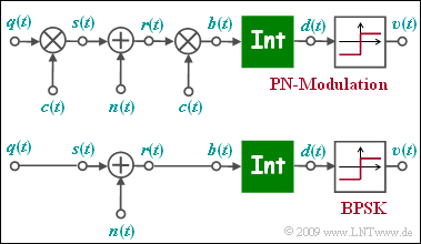
The upper figure shows the equivalent circuit diagram of PN modulation ( ''Direct Sequence Spread Spectrum'', abbreviated DS-SS) in the equivalent low-pass range, where„ $n(t)$ stands for AWGN noise. | The upper figure shows the equivalent circuit diagram of PN modulation ( ''Direct Sequence Spread Spectrum'', abbreviated DS-SS) in the equivalent low-pass range, where„ $n(t)$ stands for AWGN noise. | ||
Below, the low-pass model of binary phase modulation (BPSK) is sketched | Below, the low-pass model of binary phase modulation (BPSK) is sketched | ||
| − | *The low-pass | + | *The low-pass transmitted signal $s(t)$ is equal to the rectangular source signal $q(t) ∈ \{+1, -1\}$ with rectangular duration $T$ only for reasons of uniformity. |
*The function of the integrator can be written as follows: | *The function of the integrator can be written as follows: | ||
:$$d (\nu T) = \frac{1}{T} \cdot \int_{(\nu -1 )T }^{\nu T} \hspace{-0.03cm} b (t )\hspace{0.1cm} {\rm d}t \hspace{0.05cm}.$$ | :$$d (\nu T) = \frac{1}{T} \cdot \int_{(\nu -1 )T }^{\nu T} \hspace{-0.03cm} b (t )\hspace{0.1cm} {\rm d}t \hspace{0.05cm}.$$ | ||
Revision as of 11:37, 25 August 2020
The upper figure shows the equivalent circuit diagram of PN modulation ( Direct Sequence Spread Spectrum, abbreviated DS-SS) in the equivalent low-pass range, where„ $n(t)$ stands for AWGN noise. Below, the low-pass model of binary phase modulation (BPSK) is sketched
- The low-pass transmitted signal $s(t)$ is equal to the rectangular source signal $q(t) ∈ \{+1, -1\}$ with rectangular duration $T$ only for reasons of uniformity.
- The function of the integrator can be written as follows:
- $$d (\nu T) = \frac{1}{T} \cdot \int_{(\nu -1 )T }^{\nu T} \hspace{-0.03cm} b (t )\hspace{0.1cm} {\rm d}t \hspace{0.05cm}.$$
- The two models differ in the multiplication by the $±1$-spreading signal $c(t)$ at the transmitter and receiver, whereas of this signal $c(t)$ only the spread degree $J$ is known.
- The specification of the specific spreading sequence (M sequence or Walsh function) is not important for the solution of this task.
It has to be examined whether the lower BPSK model can also be applied with PN modulation and whether the BPSK error probability
- $$p_{\rm B} = {\rm Q} \left( \hspace{-0.05cm} \sqrt { {2 \cdot E_{\rm B}}/{N_{\rm 0}} } \hspace{0.05cm} \right )$$
is also valid for PN modulation, or how the specified equation should be modified.
Notes:
- This exercise belongs to the chapter Die Charakteristika von UMTS.
- The CDMA method used for UMTS is also known as "PN modulation".
- The nomenclature used in this task is also partly based on the PN–Modulation im Buch „Modulationsverfahren”.
Questionnaire
Sample solution
(1) Correct is the solution 3:
- This is an optimal receiver.
- Without noise, the signal $b(t)$ within each bit is constantly equal to $+1$ or $-1$.
- From the equation given for the integrator
- $$d (\nu T) = \frac{1}{T} \cdot \hspace{-0.03cm} \int_{(\nu -1 )T }^{\nu T} \hspace{-0.3cm} b (t )\hspace{0.1cm} {\rm d}t$$
- follows that $d(\nu T)$ can only take the values $±1$.
(2) Again, the solution 3 is correct:
- Im rauschfreien Fall ⇒ $n(t) = 0$ kann auf die zweifache Multiplikation mit $c(t) ∈ \{+1, -1\}$ ⇒ $c(t)^{2} = 1$ verzichtet werden, so dass das obere Modell mit dem unteren Modell identisch ist.
(3) The solution 1 is applicable:
- Since both models are identical in the noiseless case, only the noise signal has to be adjusted: $n'(t) = n(t) \cdot c(t)$.
- The solutions 2 and 3, on the other hand, are not applicable: Integration must still be done via $T = J \cdot T_{c}$ (not via $J \cdot T$) and PN modulation does not reduce the AWGN noise.
(4) The solution 3 is correct:
- The equation valid for BPSK and AWGN channel
- $$p_{\rm B} = {\rm Q} \left( \hspace{-0.05cm} \sqrt { \frac{2 \cdot E_{\rm B}}{N_{\rm 0}} } \hspace{0.05cm} \right )$$
- is therefore also applicable to PN modulation, independent of the spreading factor $J$ and the specific spreading sequence.
- For AWGN noise, the error probability is neither increased nor decreased by band spreading.
