Difference between revisions of "Aufgaben:Exercise 5.7: OFDM Transmitter using IDFT"
From LNTwww
| (22 intermediate revisions by 4 users not shown) | |||
| Line 1: | Line 1: | ||
| − | {{quiz-Header|Buchseite= | + | {{quiz-Header|Buchseite=Modulation_Methods/Implementation_of_OFDM_Systems |
}} | }} | ||
| − | [[File:P_ID1662__A_5_7.png|right|]] | + | [[File:P_ID1662__A_5_7.png|right|frame|Block diagram of the IDFT ]] |
| − | In | + | In this exercise, we take a closer look at an OFDM transmitter implemented using the "Inverse Discrete Fourier Transform" $\rm (IDFT)$. Thereby it is valid: |
| − | + | * The system has $N = 4$ carriers. | |
| − | + | * The frame duration is $T_{\ \rm R} = 0.25 \ \rm ms$. | |
| − | + | * A guard interval is not used. | |
| − | + | * In each frame $16$ bits are transmitted. | |
| + | *The upper right diagram shows the block "IDFT" of the OFDM transmitter structure. | ||
| + | *Here, four bits each result in a complex symbol according to the $\rm16–QAM$ signal space allocation sketched below left. | ||
| − | |||
| − | + | [[File:P_ID1666__A_5_7_Signalraum.png|left|frame|Suggested 16–QAM signal space allocation]] | |
| − | $$d_{\nu ,k} = \sum\limits_{\mu = 0}^{N - 1} {D_{\mu ,k} \cdot w^{ - \nu \cdot \mu } } \quad {\rm{mit}} \quad w = {\rm{e}}^{ - {\rm{j}} {\rm{2\pi}}/N}.$$ | + | <br><br><br><br><br><br><br><br><br><br> |
| − | + | Notes: | |
| − | + | *The exercise belongs to the chapter [[Modulation_Methods/Realisierung_von_OFDM-Systemen|Implementation of OFDM Systems]]. | |
| − | === | + | *Reference is also made to the chapter [[Signal_Representation/Discrete_Fourier_Transform_(DFT)|Discrete Fourier Transform]]. |
| + | *The equation of the IDFT is with $ν = 0$, ... , $N–1$: | ||
| + | ::$$\quad d_{\nu,\ k} = \sum\limits_{\mu = 0}^{N - 1} {D_{\mu, \ k} \cdot w^{ - \nu \cdot \mu } } \quad {\rm{mit}} \quad w = {\rm{e}}^{ - {\rm{j}} {\rm{2\pi}}/N}.$$ | ||
| + | <br clear=all> | ||
| + | ===Questions=== | ||
<quiz display=simple> | <quiz display=simple> | ||
| − | { | + | {Specify the maximum data bit rate of the system. |
|type="{}"} | |type="{}"} | ||
| − | $ | + | $R_{\rm B} \ = \ $ { 64 3% } $\ \rm kbit/s$ |
| − | { | + | {For the given 16-QAM signal space allocation, specify the complex carrier coefficients $D_\mu$ for the following input bit sequences. |
|type="{}"} | |type="{}"} | ||
| − | + | ${\rm Re}\big [D_0 \big ] \ = \ $ { -1.03--0.97 } $\ \ \text{for the bit sequence 1111}$ | |
| − | + | ${\rm Im}\big [D_0\big ] \ = \ $ { -1.03--0.97 } | |
| − | + | ${\rm Re}\big [D_1\big ] \ = \ $ { -1.03--0.97 } $\ \ \text{for the bit sequence 0111}$ | |
| − | + | ${\rm Im}\big [D_1\big ] \ = \ $ { 1 } | |
| − | + | ${\rm Re}\big [D_2\big ] \ = \ $ { 3 3% } $\ \ \text{for the bit sequence 1000}$ | |
| − | + | ${\rm Im}\big [D_2\big ] \ = \ $ { -3.09--2.91 } | |
| − | + | ${\rm Re}\big [D_3\big ] \ = \ $ { 3 3% } $\ \ \text{for the bit sequence 0000}$ | |
| − | + | ${\rm Im}\big [D_3\big ] \ = \ $ { 3 3% } | |
| − | { | + | {From this, calculate the discrete time domain values $d_\nu$ within the frame. |
|type="{}"} | |type="{}"} | ||
| − | Re | + | ${\rm Re}\big [d_0\big ] \ = \ $ { 4 1% } |
| − | Im | + | ${\rm Im}\big [d_0\big ] \ = \ $ { 0. } |
| − | Re | + | ${\rm Re}\big [d_1\big ] \ = \ $ { -2.02--1.98 } |
| − | Im | + | ${\rm Im}\big [d_1\big ] \ = \ $ { 2 1% } |
| − | Re | + | ${\rm Re}\big [d_2\big ] \ = \ $ { 0. } |
| − | Im | + | ${\rm Im}\big [d_2\big ] \ = \ $ { -8.08--7.92 } |
| − | Re | + | ${\rm Re}\big [d_3\big ] \ = \ $ { -6.06--5.94 } |
| − | Im | + | ${\rm Im}\big [d_3\big ] \ = \ $ { 6 1% } |
| − | { | + | {Which statements are true for the crest factor, which denotes the ratio of the peak value to the rms value of an alternating quantity? |
|type="[]"} | |type="[]"} | ||
| − | - | + | - The crest factor is rather low for an OFDM system. |
| − | + | + | + The crest factor can become very large in OFDM systems. |
| − | + | + | + A large crest factor can lead to implementation problems. |
</quiz> | </quiz> | ||
| − | === | + | ===Solution=== |
{{ML-Kopf}} | {{ML-Kopf}} | ||
| − | '''1 | + | '''(1)''' Since no guard interval is considered here, the symbol duration $T$ is equal to the frame duration $T_{\rm{R}} = 0.25 \ \rm ms$. |
| − | $$R_{\rm{B}} = \frac{1}{T_{\rm{B}}} = \frac{4 \cdot {\rm{log}_2}\hspace{0.08cm}(16)}{T} = \frac{4 \cdot 4}{0.25\,\,{\rm ms}}\hspace{0.15cm}\underline {= 64\,\,{\rm kbit/s}}.$$ | + | *For $N = 4$ carriers and $\rm 16–QAM$, the bit rate at the input is: |
| + | :$$R_{\rm{B}} = \frac{1}{T_{\rm{B}}} = \frac{4 \cdot {\rm{log}_2}\hspace{0.08cm}(16)}{T} = \frac{4 \cdot 4}{0.25\,\,{\rm ms}}\hspace{0.15cm}\underline {= 64\,\,{\rm kbit/s}}.$$ | ||
| − | |||
| − | |||
| − | |||
| − | |||
| − | |||
| − | ''' | + | '''(2)''' From the signal space allocation, it follows for the carrier coefficients $($the index $k$ is omitted$)$: |
| − | $$ | + | :$${\text{Bit sequence}}\hspace{0.2cm}1111:\hspace{0.5cm} D_0 = -1 - {\rm{j}}\hspace{0.4cm}\Rightarrow\hspace{0.3cm}{\rm Re}[D_0]\hspace{0.15cm}\underline{=-1},\hspace{0.2cm}{\rm Im}[D_0]\hspace{0.15cm}\underline{=-1},$$ |
| − | + | :$${\text{Bit sequence}}\hspace{0.2cm}0111:\hspace{0.5cm} D_1 = -1 + {\rm{j}}\hspace{0.4cm}\Rightarrow\hspace{0.3cm}{\rm Re}[D_1]\hspace{0.15cm}\underline{=-1},\hspace{0.2cm}{\rm Im}[D_1]\hspace{0.15cm}\underline{=+1},$$ | |
| − | + | :$${\text{Bit sequence}}\hspace{0.2cm}1000:\hspace{0.5cm} D_2 = +3 - 3{\rm{j}},\hspace{0.15cm}\Rightarrow\hspace{0.3cm}{\rm Re}[D_2]\hspace{0.15cm}\underline{=+3},\hspace{0.2cm}{\rm Im}[D_2]\hspace{0.15cm}\underline{=-3},$$ | |
| − | $$ | + | :$${\text{Bit sequence}}\hspace{0.2cm}0000:\hspace{0.5cm} D_3 = +3 + 3{\rm{j}}\hspace{0.2cm}\Rightarrow\hspace{0.3cm}{\rm Re}[D_3]\hspace{0.15cm}\underline{=+3},\hspace{0.2cm}{\rm Im}[D_3]\hspace{0.15cm}\underline{=+3}.$$ |
| − | $$ | ||
| − | |||
| − | '''4.''' | + | |
| + | '''(3)''' The given $\rm IDFT$ equation is with $N = 4$: | ||
| + | :$$d_{\nu } = \sum\limits_{\mu = 0}^{N - 1} {D_{\mu } \cdot {\rm{e}}^{ \hspace{0.04cm} {\rm{j}}\hspace{0.04cm}\cdot \hspace{0.04cm} \pi/2 \hspace{0.04cm}\cdot \hspace{0.04cm}\nu \hspace{0.04cm}\cdot \hspace{0.04cm} \mu } } .$$ | ||
| + | *From this we obtain for $ν = 0$, ... , $3$: | ||
| + | :$$d_0 = D_0 + D_1 +D_2 +D_3 = 4 \hspace{2.9cm}\Rightarrow\hspace{0.4cm}{\rm Re}[d_0]\hspace{0.15cm}\underline{=4},\hspace{0.2cm}{\rm Im}[d_0]\hspace{0.15cm}\underline{=0},$$ | ||
| + | :$$d_1 = D_0 + {\rm{j}} \cdot D_1 - D_2 -{\rm{j}} \cdot D_3 = -2 + 2 \cdot {\rm{j}}\hspace{0.4cm}\Rightarrow\hspace{0.4cm}{\rm Re}[d_1]\hspace{0.15cm}\underline{=-2},\hspace{0.2cm}{\rm Im}[d_1]\hspace{0.15cm}\underline{=+2},$$ | ||
| + | :$$d_2 = D_0 - D_1 + D_2 - D_3 = -8 \cdot {\rm{j}}\hspace{2.1cm}\Rightarrow\hspace{0.4cm}{\rm Re}[d_2]\hspace{0.15cm}\underline{=0},\hspace{0.2cm}{\rm Im}[d_2]\hspace{0.15cm}\underline{=-8},$$ | ||
| + | :$$d_3 = D_0 - {\rm{j}} \cdot D_1 - D_2 +{\rm{j}} \cdot D_3 = -6 + 6 \cdot {\rm{j}}\hspace{0.4cm}\Rightarrow\hspace{0.4cm}{\rm Re}[d_3]\hspace{0.15cm}\underline{=-6},\hspace{0.2cm}{\rm Im}[d_3]\hspace{0.15cm}\underline{=+6}.$$ | ||
| + | |||
| + | |||
| + | '''(4)''' The <u>last two solutions</u> are correct: | ||
| + | * For OFDM, the crest factor is rather large. | ||
| + | *This can lead to problems in terms of linearity requirements and energy efficiency for the amplifier circuits used. | ||
{{ML-Fuß}} | {{ML-Fuß}} | ||
| Line 78: | Line 89: | ||
| − | [[Category: | + | [[Category:Modulation Methods: Exercises|^5.6 Realization of OFDM Systems^]] |
Latest revision as of 19:03, 11 January 2022
In this exercise, we take a closer look at an OFDM transmitter implemented using the "Inverse Discrete Fourier Transform" $\rm (IDFT)$. Thereby it is valid:
- The system has $N = 4$ carriers.
- The frame duration is $T_{\ \rm R} = 0.25 \ \rm ms$.
- A guard interval is not used.
- In each frame $16$ bits are transmitted.
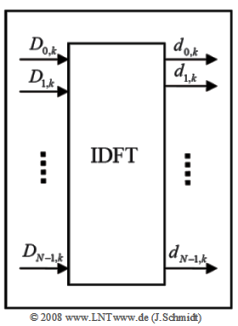
- The upper right diagram shows the block "IDFT" of the OFDM transmitter structure.
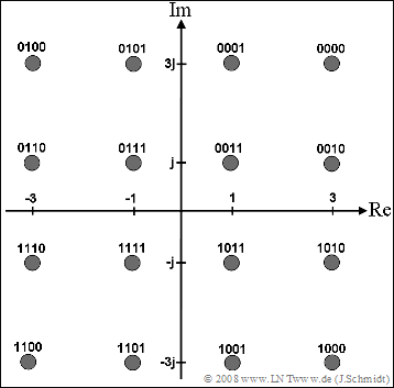
- Here, four bits each result in a complex symbol according to the $\rm16–QAM$ signal space allocation sketched below left.
Notes:
- The exercise belongs to the chapter Implementation of OFDM Systems.
- Reference is also made to the chapter Discrete Fourier Transform.
- The equation of the IDFT is with $ν = 0$, ... , $N–1$:
- $$\quad d_{\nu,\ k} = \sum\limits_{\mu = 0}^{N - 1} {D_{\mu, \ k} \cdot w^{ - \nu \cdot \mu } } \quad {\rm{mit}} \quad w = {\rm{e}}^{ - {\rm{j}} {\rm{2\pi}}/N}.$$
Questions
Solution
(1) Since no guard interval is considered here, the symbol duration $T$ is equal to the frame duration $T_{\rm{R}} = 0.25 \ \rm ms$.
- For $N = 4$ carriers and $\rm 16–QAM$, the bit rate at the input is:
- $$R_{\rm{B}} = \frac{1}{T_{\rm{B}}} = \frac{4 \cdot {\rm{log}_2}\hspace{0.08cm}(16)}{T} = \frac{4 \cdot 4}{0.25\,\,{\rm ms}}\hspace{0.15cm}\underline {= 64\,\,{\rm kbit/s}}.$$
(2) From the signal space allocation, it follows for the carrier coefficients $($the index $k$ is omitted$)$:
- $${\text{Bit sequence}}\hspace{0.2cm}1111:\hspace{0.5cm} D_0 = -1 - {\rm{j}}\hspace{0.4cm}\Rightarrow\hspace{0.3cm}{\rm Re}[D_0]\hspace{0.15cm}\underline{=-1},\hspace{0.2cm}{\rm Im}[D_0]\hspace{0.15cm}\underline{=-1},$$
- $${\text{Bit sequence}}\hspace{0.2cm}0111:\hspace{0.5cm} D_1 = -1 + {\rm{j}}\hspace{0.4cm}\Rightarrow\hspace{0.3cm}{\rm Re}[D_1]\hspace{0.15cm}\underline{=-1},\hspace{0.2cm}{\rm Im}[D_1]\hspace{0.15cm}\underline{=+1},$$
- $${\text{Bit sequence}}\hspace{0.2cm}1000:\hspace{0.5cm} D_2 = +3 - 3{\rm{j}},\hspace{0.15cm}\Rightarrow\hspace{0.3cm}{\rm Re}[D_2]\hspace{0.15cm}\underline{=+3},\hspace{0.2cm}{\rm Im}[D_2]\hspace{0.15cm}\underline{=-3},$$
- $${\text{Bit sequence}}\hspace{0.2cm}0000:\hspace{0.5cm} D_3 = +3 + 3{\rm{j}}\hspace{0.2cm}\Rightarrow\hspace{0.3cm}{\rm Re}[D_3]\hspace{0.15cm}\underline{=+3},\hspace{0.2cm}{\rm Im}[D_3]\hspace{0.15cm}\underline{=+3}.$$
(3) The given $\rm IDFT$ equation is with $N = 4$:
- $$d_{\nu } = \sum\limits_{\mu = 0}^{N - 1} {D_{\mu } \cdot {\rm{e}}^{ \hspace{0.04cm} {\rm{j}}\hspace{0.04cm}\cdot \hspace{0.04cm} \pi/2 \hspace{0.04cm}\cdot \hspace{0.04cm}\nu \hspace{0.04cm}\cdot \hspace{0.04cm} \mu } } .$$
- From this we obtain for $ν = 0$, ... , $3$:
- $$d_0 = D_0 + D_1 +D_2 +D_3 = 4 \hspace{2.9cm}\Rightarrow\hspace{0.4cm}{\rm Re}[d_0]\hspace{0.15cm}\underline{=4},\hspace{0.2cm}{\rm Im}[d_0]\hspace{0.15cm}\underline{=0},$$
- $$d_1 = D_0 + {\rm{j}} \cdot D_1 - D_2 -{\rm{j}} \cdot D_3 = -2 + 2 \cdot {\rm{j}}\hspace{0.4cm}\Rightarrow\hspace{0.4cm}{\rm Re}[d_1]\hspace{0.15cm}\underline{=-2},\hspace{0.2cm}{\rm Im}[d_1]\hspace{0.15cm}\underline{=+2},$$
- $$d_2 = D_0 - D_1 + D_2 - D_3 = -8 \cdot {\rm{j}}\hspace{2.1cm}\Rightarrow\hspace{0.4cm}{\rm Re}[d_2]\hspace{0.15cm}\underline{=0},\hspace{0.2cm}{\rm Im}[d_2]\hspace{0.15cm}\underline{=-8},$$
- $$d_3 = D_0 - {\rm{j}} \cdot D_1 - D_2 +{\rm{j}} \cdot D_3 = -6 + 6 \cdot {\rm{j}}\hspace{0.4cm}\Rightarrow\hspace{0.4cm}{\rm Re}[d_3]\hspace{0.15cm}\underline{=-6},\hspace{0.2cm}{\rm Im}[d_3]\hspace{0.15cm}\underline{=+6}.$$
(4) The last two solutions are correct:
- For OFDM, the crest factor is rather large.
- This can lead to problems in terms of linearity requirements and energy efficiency for the amplifier circuits used.

