Difference between revisions of "Linear and Time Invariant Systems/System Description in Time Domain"
Tag: Undo |
Tag: Undo |
||
| Line 6: | Line 6: | ||
}} | }} | ||
| − | ==Impulse | + | ==Impulse response== |
<br> | <br> | ||
| − | + | Auf der Seite [[Signal_Representation/Fourier_Transform_and_Its_Inverse#Das_erste_Fourierintegral|Das erste Fourierintegral]] im Buch „Signaldarstellung” wurde dargelegt, dass für jedes deterministische Signal $x(t)$ mit Hilfe der Fouriertransformation eine Spektralfunktion $X(f)$ angegeben werden kann. Oft bezeichnet man $X(f)$ kurz als das Spektrum. | |
| − | + | Alle Informationen über die Spektralfunktion sind aber auch bereits in der Zeitbereichsdarstellung enthalten, wenn auch nicht immer sofort erkennbar. Der gleiche Sachverhalt trifft für lineare zeitinvariante Systeme zu. | |
| − | {{ | + | {{BlaueBox|TEXT= |
$\text{Definition:}$ | $\text{Definition:}$ | ||
| − | + | Die wichtigste Beschreibungsgröße eines linearen zeitinvarianten Systems im Zeitbereich ist die Fourierrücktransformierte von $H(f)$, die man als die '''Impulsantwort''' bezeichnet: | |
:$$h(t) = \int_{-\infty}^{+\infty}H(f) \cdot {\rm e}^{\hspace{0.05cm}{\rm j}2\pi ft}\hspace{0.15cm} {\rm d}f.$$}} | :$$h(t) = \int_{-\infty}^{+\infty}H(f) \cdot {\rm e}^{\hspace{0.05cm}{\rm j}2\pi ft}\hspace{0.15cm} {\rm d}f.$$}} | ||
| − | + | Hierzu ist Folgendes anzumerken: | |
| − | * | + | *Der Frequenzgang $H(f)$ und die Impulsantwort $h(t)$ sind äquivalente Beschreibungsgrößen, die genau die gleichen Informationen über das LZI–System beinhalten. |
| − | * | + | *Verwendet man das diracförmige Eingangssignal $x(t) = δ(t)$, so ist $X(f) = 1$ zu setzen und es gilt $Y(f) = H(f)$ bzw. $y(t) = h(t)$. |
| − | * | + | *Die Bezeichnung „Impulsantwort” spiegelt diese Aussage wieder: $h(t)$ ist die Antwort des Systems auf einen (Dirac-)Impuls am Eingang. |
| − | * | + | *Die obige Definition lässt erkennen, dass jede Impulsantwort die Einheit $\text{Hz = 1/s}$ besitzen muss. |
| − | [[File: | + | [[File:P_ID837__LZI_T_1_2_S1_neu.png|right|frame|Rechteckförmige Impulsantwort und zugehöriges Betragsspektrum|class=fit]] |
| − | {{ | + | {{GraueBox|TEXT= |
| − | $\text{ | + | $\text{Beispiel 1:}$ |
| − | + | Die Impulsantwort $h(t)$ des so genannten ''Spalt–Tiefpasses'' ist über eine Zeitdauer $T$ hinweg konstant und außerhalb dieses Zeitintervalls gleich Null. | |
| − | * | + | *Der dazugehörige Amplitudengang als der Betrag des Frequenzgangs ist |
| − | :$$\vert H(f)\vert = \vert {\rm si}(\pi fT)\vert .$$ | + | :$$\vert H(f)\vert = \vert {\rm si}(\pi fT)\vert .$$ |
| − | * | + | *Die Fläche über $h(t)$ ist gleich $H(f = 0) = 1$. Daraus folgt: <br> Im Bereich $ 0 < t < T$ muss die Impulsantwort gleich $1/T$ sein. |
| − | * | + | *Der Phasenverlauf ergibt sich zu |
| − | :$$b(f) = \left\{ \begin{array}{l} \hspace{0.25cm}\pi/T \ - \pi/T \end{array} \right.\quad \quad\begin{array}{*{20}c} \text{ | + | :$$b(f) = \left\{ \begin{array}{l} \hspace{0.25cm}\pi/T \\ - \pi/T \\ \end{array} \right.\quad \quad\begin{array}{*{20}c} \text{für} \\ \text{für} \\ \end{array}\begin{array}{*{20}c}{\left \vert \hspace{0.05cm} f\hspace{0.05cm} \right \vert > 0,} \\{\vert \hspace{0.05cm} f \hspace{0.05cm} \vert < 0.} \\\end{array}$$ |
| − | * | + | *Bei symmetrischem $h(t)$ um $t = 0$ (also akausal) wäre $b(f)=0$. }} |
| − | + | ==Einige Gesetze der Fouriertransformation== | |
| − | == | ||
<br> | <br> | ||
| − | + | Die [[Signal_Representation/Fourier_Transform_Laws|Gesetzmäßigkeiten der Fouriertransformation]] wurden bereits im Buch „Signaldarstellung” ausführlich dargelegt. | |
| − | + | Hier folgt nun eine kurze Zusammenfassung, wobei $H(f)$ den Frequenzgang eines LZI–Systems beschreibt und dessen Fourierrücktransformierte $h(t)$ die Impulsantwort ist. Diese Gesetzmäßigkeiten werden in den [[Linear_and_Time_Invariant_Systems/Systembeschreibung_im_Zeitbereich#Aufgaben_zum_Kapitel|Aufgaben]] zu diesem Kapitel „Systemtheoretische Grundlagen” häufiger angewendet. | |
| − | + | Wir verweisen hier auch auf das Lernvideo [[Gesetzmäßigkeiten_der_Fouriertransformation_(Lernvideo)|Gesetzmäßigkeiten der Fouriertransformation]]. | |
| − | + | Bei den folgenden Gleichungen wird das Kurzsymbol der Fouriertransformation benutzt. Der ausgefüllte Kreis kennzeichnet den Spektralbereich, der weiße den Zeitbereich. | |
| − | *''' | + | *'''Multiplikation''' mit einem konstanten Faktor: |
| − | :$$k \cdot H(f)\bullet\!\!\!\!\!\!\!\circ\,k \cdot h(t).$$ | + | :$$k \cdot H(f)\bullet\!\!-\!\!\!-\!\!\!-\!\!\circ\,k \cdot h(t).$$ |
| − | : | + | :Bei $k \lt 1$ spricht man von einer Dämpfung, während $k \gt 1$ für eine Verstärkung steht. |
| − | *'' | + | *'''Ähnlichkeitssatz''': |
| − | :$$H({f}/{k})\bullet\!\!-\!\!-\!\!-\!\!\circ\,|k| \cdot h(k\cdot t).$$ | + | :$$H({f}/{k})\bullet\!\!-\!\!\!-\!\!\!-\!\!\circ\,|k| \cdot h(k\cdot t).$$ |
| − | :# | + | :# Dieser besagt: Eine Stauchung $(k < 1)$ des Frequenzgangs führt zu einer breiteren und niedrigeren Impulsantwort. |
| − | :# | + | :# Durch Streckung $(k > 1)$ von $H(f)$ wird $h(t)$ schmaler und höher. |
| − | *''' | + | *'''Verschiebungssatz''' im Frequenzbereich und im Zeitbereich: |
| − | :$$H(f - f_0) \bullet\!\!\!\!\!\!\!\circ\, h( t )\cdot {\rm e}^{\hspace{0.05cm}{\rm j}2\pi f_0 t},\hspace{0.9cm} | + | :$$H(f - f_0) \bullet\!\!-\!\!\!-\!\!\!-\!\!\circ\, h( t )\cdot {\rm e}^{\hspace{0.05cm}{\rm j}2\pi f_0 t},\hspace{0.9cm} |
| − | H(f) \cdot {\rm e}^{-{\rm j}2\pi ft_0}\bullet\!\!-\!\!-\!\!-\!\!\circ\, h( t- t_0 ).$$ | + | H(f) \cdot {\rm e}^{-{\rm j}2\pi ft_0}\bullet\!\!-\!\!\!-\!\!\!-\!\!\circ\, h( t- t_0 ).$$ |
| − | :# | + | :# Eine Verschiebung um $t_0$ (Laufzeit) führt also im Frequenzbereich zu der Multiplikation mit einer komplexen Exponentialfunktion. |
| − | :# | + | :# Der Amplitudengang $|H(f)|$ wird dadurch nicht verändert. |
| − | *'' | + | *'''Differentiationssatz''' im Frequenzbereich und im Zeitbereich: |
| − | :$$\frac{1}{{\rm j}2\pi }} \cdot \frac{{\rm d}H( f )}}{{\rm d}f}} \bullet\!\!\!\!\!\!\!\circ\,- t \cdot h( t ),\hspace{0.9cm} | + | :$$\frac{1}{{{\rm j}2\pi }} \cdot \frac{{{\rm d}H( f )}}{{{\rm d}f}} \bullet\!\!-\!\!\!-\!\!\!-\!\!\circ\,- t \cdot h( t ),\hspace{0.9cm} |
| − | {\rm j}\cdot 2\pi f \cdot H( f ){}\bullet\!\!\! | + | {\rm j}\cdot 2\pi f \cdot H( f ){}\bullet\!\!-\!\!\!-\!\!\!-\!\!\circ\, \frac{{{\rm d}h( t )}}{{\rm d}t}.$$ |
| − | : | + | :Ein differenzierendes Element im LZI–System führt im Frequenzbereich zu einer Multiplikation mit ${\rm j}\cdot 2πf$ und damit unter Anderem zu einer Phasendrehung um $90^{\circ}$. |
| − | == | + | ==Kausale Systeme== |
<br> | <br> | ||
| − | {{ | + | {{BlaueBox|TEXT= |
$\text{Definition:}$ | $\text{Definition:}$ | ||
| − | + | Ein LZI–System bezeichnet man dann als '''kausal''', wenn die Impulsantwort $h(t)$ – also die Fourierrücktransformierte des Frequenzgangs $H(f)$ – folgende Bedingung erfüllt: | |
:$$h(t) = 0 \hspace{0.25cm}{\rm f\ddot{u}r}\hspace{0.25cm} t < 0.$$ | :$$h(t) = 0 \hspace{0.25cm}{\rm f\ddot{u}r}\hspace{0.25cm} t < 0.$$ | ||
| − | $\text{ | + | $\text{Bitte beachten Sie:}$ Jedes realisierbare System ist kausal. }} |
| − | [[File: | + | [[File:P_ID806__LZI_T_1_2_S3_neu.png|right|frame|Akausales System $\rm A$ und kausales System $\rm B$|class=fit]] |
| − | {{ | + | {{GraueBox|TEXT= |
| − | $\text{ | + | $\text{Beispiel 2:}$ |
| − | + | Die Grafik verdeutlicht den Unterschied zwischen dem akausalen System $\rm A$ und dem kausalen System $\rm B$. | |
| − | * | + | *Beim System $\rm A$ beginnt die Wirkung früher $($bei $t =\hspace{0.05cm} –T)$ als die Ursache $($Diracfunktion bei $t = 0)$, was natürlich in der Praxis nicht möglich ist. |
| − | * | + | *Fast alle akausalen Systeme lassen sich unter Verwendung einer Laufzeit $\tau$ in ein realisierbares kausales System überführen. |
| − | * | + | *Zum Beispiel gilt mit $\tau = T$: |
| − | :$$h_{\rm B}(t) = h_{\rm A}(t - T).$$} | + | :$$h_{\rm B}(t) = h_{\rm A}(t - T).$$}} |
| − | * | + | *Für kausale Systeme gelten alle bisher gemachten Aussagen ebenso wie für akausale Systeme. |
| − | * | + | *Zur Beschreibung kausaler Systeme lassen sich jedoch einige spezifische Eigenschaften nutzen, wie im dritten Hauptkapitel „Beschreibung kausaler realisierbarer Systeme” [[Lineare_zeitinvariante_Systeme|dieses Buches]] ausgeführt wird. |
| − | {{ | + | {{BlaueBox|TEXT= |
| − | In | + | In diesem ersten und dem folgenden zweiten Hauptkapitel betrachten wir vorwiegend akausale Systeme, da deren mathematische Beschreibung meist einfacher ist. |
| − | *So | + | *So ist der Frequenzgang $H_{\rm A}(f)$ reell, |
| − | * | + | *während für $H_{\rm B}(f)$ der zusätzliche Term ${\rm e}^{–{\rm j2π}f\hspace{0.05cm}T}$ zu berücksichtigen ist. }} |
| − | == | + | ==Berechnung des Ausgangssignals== |
<br> | <br> | ||
| − | + | Wir betrachten die folgende Aufgabenstellung: Bekannt sei das Eingangssignal $x(t)$ und der Frequenzgang $H(f)$. Gesucht ist das Ausgangssignal $y(t)$. | |
| − | [[File:EN_LZI_T_1_2_S4.png|right|frame| | + | [[File:EN_LZI_T_1_2_S4.png|right|frame|Zur Ermittlung der Ausgangsgrößen eines LZI–Systems|class=fit]] |
| − | + | Soll die Lösung im Frequenzbereich erfolgen, so muss zunächst aus dem gegebenen Eingangssignal $x(t)$ durch [[Signal_Representation/Fourier_Transform_and_Its_Inverse#Das_erste_Fourierintegral|Fouriertransformation]] das Spektrum $X(f)$ ermittelt und mit dem Frequenzgang $H(f)$ multipliziert werden. Durch [[Signal_Representation/Fourier_Transform_and_Its_Inverse#Das_zweite_Fourierintegral|Fourierrücktransformation]] des Produkts kommt man dann zum Signal $y(t)$. | |
| − | + | Hier nochmals der gesamte Rechengang zusammengefasst: | |
| − | :$${\rm 1.\,\, | + | :$${\rm 1.\,\, Schritt\hspace{-0.1cm} :}\hspace{0.5cm} X(f)\bullet\!\!-\!\!\!-\!\!\!-\!\!\circ\, x( t )\hspace{1.55cm}{\rm Eingangsspektrum},$$ |
| − | :$${\rm 2.\,\, | + | :$${\rm 2.\,\, Schritt\hspace{-0.1cm}:}\hspace{0.5cm}Y(f)= X(f) \cdot H(f) \hspace{0.82cm}{\rm Ausgangsspektrum},$$ |
| − | :$${\rm 3.\,\, | + | :$${\rm 3.\,\, Schritt\hspace{-0.1cm}:}\hspace{0.5cm} y(t)\circ\!\!-\!\!\!-\!\!\!-\!\!\bullet\, Y(f )\hspace{1.55cm}{\rm Ausgangssignal}.$$ |
| − | + | Zum gleichen Ergebnis kommt man nach der Berechnung im Zeitbereich, indem man zunächst aus dem Frequenzgang $H(f)$ mittels Fourierrücktransformation die Impulsantwort $h(t)$ berechnet und anschließend die Faltungsoperation anwendet: | |
| − | :$$y(t) = x (t) * h (t) = \int_{ - \infty }^{ + \infty } {x ( \tau )} \cdot h ( {t - \tau } ) \hspace{0.1cm}{\rm d}\tau.$$ | + | :$$y(t) = x (t) * h (t) = \int_{ - \infty }^{ + \infty } {x ( \tau )} \cdot h ( {t - \tau } ) \hspace{0.1cm}{\rm d}\tau.$$ |
| − | * | + | *Die Ergebnisse sind bei beiden Vorgehensweisen identisch. |
| − | * | + | *Zweckmäßigerweise sollte man dasjenige Verfahren auswählen, das mit weniger Rechenaufwand zum Ziel führt. |
| − | {{ | + | {{GraueBox|TEXT= |
| − | $\text{ | + | $\text{Beispiel 3:}$ |
| − | + | Am Eingang eines Spalt–Tiefpasses mit rechteckförmiger Impulsantwort der Breite $T$ (siehe [[Linear_and_Time_Invariant_Systems/Systembeschreibung_im_Zeitbereich#Impulsantwort|$\text{Beispiel 1}$]]) liegt ein Rechteckimpuls $x(t)$ der Dauer $2T$ an. | |
| − | [[File: | + | [[File:P_ID812__LZI_T_1_2_S4b_neu.png|right|frame|Trapezförmiger Ausgangsimpuls, da $x(t)$ und $h(t)$ rechteckförmig sind|class=fit]] |
| − | In | + | In diesem Fall ist die direkte Berechnung im Zeitbereich günstiger: |
| − | * | + | *Die Faltung zweier unterschiedlich breiter Rechtecke $x(t)$ und $h(t)$ führt zum trapezförmigen Ausgangsimpuls $y(t)$. |
| − | * | + | *Man erkennt die Tiefpasseigenschaft des Filters an der endlichen Flankensteilheit von $y(t)$. |
| − | * | + | *Die Impulshöhe $3\text{ V}$ bleibt in diesem Beispiel erhalten, wegen |
| − | :$$H(f = 0) = 1/T | + | :$$H(f = 0) = 1/T · T = 1.$$ }} |
==Step response== | ==Step response== | ||
<br> | <br> | ||
| − | {{ | + | {{BlaueBox|TEXT= |
| − | $\text{ | + | $\text{Definitionen:}$ |
| − | + | Eine in der Praxis oft verwendete Eingangsfunktion $x(t)$ zur Messung von $H(f)$ ist die '''Sprungfunktion''' | |
| − | :$${\rm \gamma}(t) = \left\{ \begin{array}{l} \hspace{0.25cm}0 \\ 0.5 \ \hspace{0.25cm} 1 \ \end{array} \right.\quad \quad\begin{array}{*{20}c} \text{ | + | :$${\rm \gamma}(t) = \left\{ \begin{array}{l} \hspace{0.25cm}0 \\ 0.5 \\ \hspace{0.25cm} 1 \\ \end{array} \right.\quad \quad\begin{array}{*{20}c} \text{für} \\ \text{für}\\ \text{für} \\ \end{array}\begin{array}{*{20}c}{\vert \hspace{0.05cm} t\hspace{0.05cm} \vert < 0,} \\ {\vert \hspace{0.05cm}t\hspace{0.05cm} \vert = 0,} \\ {\vert \hspace{0.05cm} t \hspace{0.05cm} \vert > 0.} \\ \end{array}$$ |
| − | + | Die '''Sprungantwort''' $\sigma(t)$ ist die Antwort des Systems, wenn man an den Eingang die Sprungfunktion $\gamma(t)$ anlegt: | |
| − | :$$x(t) = {\rm \gamma}(t)\hspace{0.5cm}\Rightarrow \hspace{0.5cm} y(t) = {\rm \sigma}(t).$$} | + | :$$x(t) = {\rm \gamma}(t)\hspace{0.5cm}\Rightarrow \hspace{0.5cm} y(t) = {\rm \sigma}(t).$$}} |
| − | + | Die Berechnung im Frequenzbereich wäre hier etwas umständlich, denn man müsste dann folgende Gleichung anwenden: | |
| − | :$${\rm \sigma}(t)\circ\!\!\!\!\!\!\!\!\bullet\, X(f ) \cdot H(f) =\left({1}/{2}\cdot \delta(f) + \frac{1}{{\rm j}\cdot 2\pi f} \right) \cdot H(f).$$ | + | :$${\rm \sigma}(t)\circ\!\!-\!\!\!-\!\!\!-\!\!\bullet\, X(f ) \cdot H(f) =\left({1}/{2}\cdot \delta(f) + \frac{1}{{\rm j}\cdot 2\pi f} \right) \cdot H(f).$$ |
| − | + | Die Berechnung im Zeitbereich führt dagegen direkt zum Ergebnis: | |
| − | :$${\rm \sigma}(t) = \int_{ - \infty }^{ t } {h ( \tau )} \hspace{0.1cm}{\rm d}\tau.$$ | + | :$${\rm \sigma}(t) = \int_{ - \infty }^{ t } {h ( \tau )} \hspace{0.1cm}{\rm d}\tau.$$ |
| − | + | Bei kausalen Systemen gilt $h(\tau) = 0$ für $\tau \lt 0$, so dass die untere Integrationsgrenze in obiger Gleichung zu $\tau = 0$ gesetzt werden kann. | |
| − | {{ | + | {{BlaueBox|TEXT= |
| − | $\text{ | + | $\text{Beweis:}$ |
| − | + | Das genannte Ergebnis ist auch aus folgendem Grunde einsichtig: | |
| − | * | + | *Die Sprungfunktion $\gamma(t)$ hängt mit der Diracfunktion $\delta(t)$ wie folgt zusammen: |
| − | :$${\rm \gamma}(t) = \int_{ - \infty }^{ t } {\delta ( \tau )} \hspace{0.1cm}{\rm d}\tau.$$ | + | :$${\rm \gamma}(t) = \int_{ - \infty }^{ t } {\delta ( \tau )} \hspace{0.1cm}{\rm d}\tau.$$ |
| − | * | + | *Da wir Linearität vorausgesetzt haben und die Integration eine lineare Operation darstellt, gilt auch für das Ausgangssignal der entsprechende Zusammenhang: |
| − | :$${\rm \sigma}(t) = \int_{ - \infty }^{ t } {h ( \tau )} \hspace{0.1cm}{\rm d}\tau.$$ | + | :$${\rm \sigma}(t) = \int_{ - \infty }^{ t } {h ( \tau )} \hspace{0.1cm}{\rm d}\tau.$$ |
<div align="right">q.e.d.</div>}} | <div align="right">q.e.d.</div>}} | ||
| − | [[File:EN_LZI_T_1_2_S5.png|right|frame| | + | [[File:EN_LZI_T_1_2_S5.png|right|frame|Berechnung der Sprungantwort bei rechteckförmiger Impulsantwort|class=fit]] |
| − | {{ | + | {{GraueBox|TEXT= |
| − | $\text{ | + | $\text{Beispiel 4:}$ |
| − | + | Die Grafik verdeutlicht den Sachverhalt für die Rechteck–Impulsantwort $h(\tau)$. | |
| − | * | + | * Die Abszisse wurde in $\tau$ umbenannt. |
| − | * | + | *Blau eingezeichnet ist die Sprungfunktion $\gamma(\tau)$. |
| − | * | + | *Durch Spiegelung und Verschiebung erhält man $\gamma(t - \tau)$ ⇒ violett gestrichelte Kurve. |
| − | * | + | *Die rot hinterlegte Fläche gibt somit die Sprungantwort $\sigma(\tau)$ zum Zeitpunkt $\tau = t$ an.}} |
Revision as of 01:59, 19 April 2021
Contents
Impulse response
Auf der Seite Das erste Fourierintegral im Buch „Signaldarstellung” wurde dargelegt, dass für jedes deterministische Signal $x(t)$ mit Hilfe der Fouriertransformation eine Spektralfunktion $X(f)$ angegeben werden kann. Oft bezeichnet man $X(f)$ kurz als das Spektrum.
Alle Informationen über die Spektralfunktion sind aber auch bereits in der Zeitbereichsdarstellung enthalten, wenn auch nicht immer sofort erkennbar. Der gleiche Sachverhalt trifft für lineare zeitinvariante Systeme zu.
$\text{Definition:}$ Die wichtigste Beschreibungsgröße eines linearen zeitinvarianten Systems im Zeitbereich ist die Fourierrücktransformierte von $H(f)$, die man als die Impulsantwort bezeichnet:
- $$h(t) = \int_{-\infty}^{+\infty}H(f) \cdot {\rm e}^{\hspace{0.05cm}{\rm j}2\pi ft}\hspace{0.15cm} {\rm d}f.$$
Hierzu ist Folgendes anzumerken:
- Der Frequenzgang $H(f)$ und die Impulsantwort $h(t)$ sind äquivalente Beschreibungsgrößen, die genau die gleichen Informationen über das LZI–System beinhalten.
- Verwendet man das diracförmige Eingangssignal $x(t) = δ(t)$, so ist $X(f) = 1$ zu setzen und es gilt $Y(f) = H(f)$ bzw. $y(t) = h(t)$.
- Die Bezeichnung „Impulsantwort” spiegelt diese Aussage wieder: $h(t)$ ist die Antwort des Systems auf einen (Dirac-)Impuls am Eingang.
- Die obige Definition lässt erkennen, dass jede Impulsantwort die Einheit $\text{Hz = 1/s}$ besitzen muss.
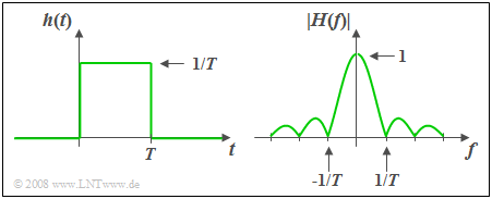
$\text{Beispiel 1:}$ Die Impulsantwort $h(t)$ des so genannten Spalt–Tiefpasses ist über eine Zeitdauer $T$ hinweg konstant und außerhalb dieses Zeitintervalls gleich Null.
- Der dazugehörige Amplitudengang als der Betrag des Frequenzgangs ist
- $$\vert H(f)\vert = \vert {\rm si}(\pi fT)\vert .$$
- Die Fläche über $h(t)$ ist gleich $H(f = 0) = 1$. Daraus folgt:
Im Bereich $ 0 < t < T$ muss die Impulsantwort gleich $1/T$ sein. - Der Phasenverlauf ergibt sich zu
- $$b(f) = \left\{ \begin{array}{l} \hspace{0.25cm}\pi/T \\ - \pi/T \\ \end{array} \right.\quad \quad\begin{array}{*{20}c} \text{für} \\ \text{für} \\ \end{array}\begin{array}{*{20}c}{\left \vert \hspace{0.05cm} f\hspace{0.05cm} \right \vert > 0,} \\{\vert \hspace{0.05cm} f \hspace{0.05cm} \vert < 0.} \\\end{array}$$
- Bei symmetrischem $h(t)$ um $t = 0$ (also akausal) wäre $b(f)=0$.
Einige Gesetze der Fouriertransformation
Die Gesetzmäßigkeiten der Fouriertransformation wurden bereits im Buch „Signaldarstellung” ausführlich dargelegt.
Hier folgt nun eine kurze Zusammenfassung, wobei $H(f)$ den Frequenzgang eines LZI–Systems beschreibt und dessen Fourierrücktransformierte $h(t)$ die Impulsantwort ist. Diese Gesetzmäßigkeiten werden in den Aufgaben zu diesem Kapitel „Systemtheoretische Grundlagen” häufiger angewendet.
Wir verweisen hier auch auf das Lernvideo Gesetzmäßigkeiten der Fouriertransformation.
Bei den folgenden Gleichungen wird das Kurzsymbol der Fouriertransformation benutzt. Der ausgefüllte Kreis kennzeichnet den Spektralbereich, der weiße den Zeitbereich.
- Multiplikation mit einem konstanten Faktor:
- $$k \cdot H(f)\bullet\!\!-\!\!\!-\!\!\!-\!\!\circ\,k \cdot h(t).$$
- Bei $k \lt 1$ spricht man von einer Dämpfung, während $k \gt 1$ für eine Verstärkung steht.
- Ähnlichkeitssatz:
- $$H({f}/{k})\bullet\!\!-\!\!\!-\!\!\!-\!\!\circ\,|k| \cdot h(k\cdot t).$$
- Dieser besagt: Eine Stauchung $(k < 1)$ des Frequenzgangs führt zu einer breiteren und niedrigeren Impulsantwort.
- Durch Streckung $(k > 1)$ von $H(f)$ wird $h(t)$ schmaler und höher.
- Verschiebungssatz im Frequenzbereich und im Zeitbereich:
- $$H(f - f_0) \bullet\!\!-\!\!\!-\!\!\!-\!\!\circ\, h( t )\cdot {\rm e}^{\hspace{0.05cm}{\rm j}2\pi f_0 t},\hspace{0.9cm}
H(f) \cdot {\rm e}^{-{\rm j}2\pi ft_0}\bullet\!\!-\!\!\!-\!\!\!-\!\!\circ\, h( t- t_0 ).$$
- Eine Verschiebung um $t_0$ (Laufzeit) führt also im Frequenzbereich zu der Multiplikation mit einer komplexen Exponentialfunktion.
- Der Amplitudengang $|H(f)|$ wird dadurch nicht verändert.
- Differentiationssatz im Frequenzbereich und im Zeitbereich:
- $$\frac{1}{{{\rm j}2\pi }} \cdot \frac{{{\rm d}H( f )}}{{{\rm d}f}} \bullet\!\!-\!\!\!-\!\!\!-\!\!\circ\,- t \cdot h( t ),\hspace{0.9cm} {\rm j}\cdot 2\pi f \cdot H( f ){}\bullet\!\!-\!\!\!-\!\!\!-\!\!\circ\, \frac{{{\rm d}h( t )}}{{\rm d}t}.$$
- Ein differenzierendes Element im LZI–System führt im Frequenzbereich zu einer Multiplikation mit ${\rm j}\cdot 2πf$ und damit unter Anderem zu einer Phasendrehung um $90^{\circ}$.
Kausale Systeme
$\text{Definition:}$ Ein LZI–System bezeichnet man dann als kausal, wenn die Impulsantwort $h(t)$ – also die Fourierrücktransformierte des Frequenzgangs $H(f)$ – folgende Bedingung erfüllt:
- $$h(t) = 0 \hspace{0.25cm}{\rm f\ddot{u}r}\hspace{0.25cm} t < 0.$$
$\text{Bitte beachten Sie:}$ Jedes realisierbare System ist kausal.
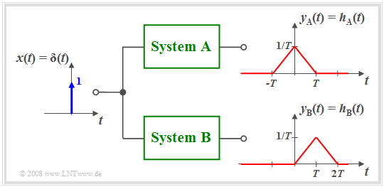
$\text{Beispiel 2:}$ Die Grafik verdeutlicht den Unterschied zwischen dem akausalen System $\rm A$ und dem kausalen System $\rm B$.
- Beim System $\rm A$ beginnt die Wirkung früher $($bei $t =\hspace{0.05cm} –T)$ als die Ursache $($Diracfunktion bei $t = 0)$, was natürlich in der Praxis nicht möglich ist.
- Fast alle akausalen Systeme lassen sich unter Verwendung einer Laufzeit $\tau$ in ein realisierbares kausales System überführen.
- Zum Beispiel gilt mit $\tau = T$:
- $$h_{\rm B}(t) = h_{\rm A}(t - T).$$
- Für kausale Systeme gelten alle bisher gemachten Aussagen ebenso wie für akausale Systeme.
- Zur Beschreibung kausaler Systeme lassen sich jedoch einige spezifische Eigenschaften nutzen, wie im dritten Hauptkapitel „Beschreibung kausaler realisierbarer Systeme” dieses Buches ausgeführt wird.
In diesem ersten und dem folgenden zweiten Hauptkapitel betrachten wir vorwiegend akausale Systeme, da deren mathematische Beschreibung meist einfacher ist.
- So ist der Frequenzgang $H_{\rm A}(f)$ reell,
- während für $H_{\rm B}(f)$ der zusätzliche Term ${\rm e}^{–{\rm j2π}f\hspace{0.05cm}T}$ zu berücksichtigen ist.
Berechnung des Ausgangssignals
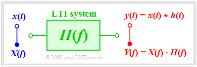
Wir betrachten die folgende Aufgabenstellung: Bekannt sei das Eingangssignal $x(t)$ und der Frequenzgang $H(f)$. Gesucht ist das Ausgangssignal $y(t)$.
Soll die Lösung im Frequenzbereich erfolgen, so muss zunächst aus dem gegebenen Eingangssignal $x(t)$ durch Fouriertransformation das Spektrum $X(f)$ ermittelt und mit dem Frequenzgang $H(f)$ multipliziert werden. Durch Fourierrücktransformation des Produkts kommt man dann zum Signal $y(t)$.
Hier nochmals der gesamte Rechengang zusammengefasst:
- $${\rm 1.\,\, Schritt\hspace{-0.1cm} :}\hspace{0.5cm} X(f)\bullet\!\!-\!\!\!-\!\!\!-\!\!\circ\, x( t )\hspace{1.55cm}{\rm Eingangsspektrum},$$
- $${\rm 2.\,\, Schritt\hspace{-0.1cm}:}\hspace{0.5cm}Y(f)= X(f) \cdot H(f) \hspace{0.82cm}{\rm Ausgangsspektrum},$$
- $${\rm 3.\,\, Schritt\hspace{-0.1cm}:}\hspace{0.5cm} y(t)\circ\!\!-\!\!\!-\!\!\!-\!\!\bullet\, Y(f )\hspace{1.55cm}{\rm Ausgangssignal}.$$
Zum gleichen Ergebnis kommt man nach der Berechnung im Zeitbereich, indem man zunächst aus dem Frequenzgang $H(f)$ mittels Fourierrücktransformation die Impulsantwort $h(t)$ berechnet und anschließend die Faltungsoperation anwendet:
- $$y(t) = x (t) * h (t) = \int_{ - \infty }^{ + \infty } {x ( \tau )} \cdot h ( {t - \tau } ) \hspace{0.1cm}{\rm d}\tau.$$
- Die Ergebnisse sind bei beiden Vorgehensweisen identisch.
- Zweckmäßigerweise sollte man dasjenige Verfahren auswählen, das mit weniger Rechenaufwand zum Ziel führt.
$\text{Beispiel 3:}$ Am Eingang eines Spalt–Tiefpasses mit rechteckförmiger Impulsantwort der Breite $T$ (siehe $\text{Beispiel 1}$) liegt ein Rechteckimpuls $x(t)$ der Dauer $2T$ an.
In diesem Fall ist die direkte Berechnung im Zeitbereich günstiger:
- Die Faltung zweier unterschiedlich breiter Rechtecke $x(t)$ und $h(t)$ führt zum trapezförmigen Ausgangsimpuls $y(t)$.
- Man erkennt die Tiefpasseigenschaft des Filters an der endlichen Flankensteilheit von $y(t)$.
- Die Impulshöhe $3\text{ V}$ bleibt in diesem Beispiel erhalten, wegen
- $$H(f = 0) = 1/T · T = 1.$$
Step response
$\text{Definitionen:}$ Eine in der Praxis oft verwendete Eingangsfunktion $x(t)$ zur Messung von $H(f)$ ist die Sprungfunktion
- $${\rm \gamma}(t) = \left\{ \begin{array}{l} \hspace{0.25cm}0 \\ 0.5 \\ \hspace{0.25cm} 1 \\ \end{array} \right.\quad \quad\begin{array}{*{20}c} \text{für} \\ \text{für}\\ \text{für} \\ \end{array}\begin{array}{*{20}c}{\vert \hspace{0.05cm} t\hspace{0.05cm} \vert < 0,} \\ {\vert \hspace{0.05cm}t\hspace{0.05cm} \vert = 0,} \\ {\vert \hspace{0.05cm} t \hspace{0.05cm} \vert > 0.} \\ \end{array}$$
Die Sprungantwort $\sigma(t)$ ist die Antwort des Systems, wenn man an den Eingang die Sprungfunktion $\gamma(t)$ anlegt:
- $$x(t) = {\rm \gamma}(t)\hspace{0.5cm}\Rightarrow \hspace{0.5cm} y(t) = {\rm \sigma}(t).$$
Die Berechnung im Frequenzbereich wäre hier etwas umständlich, denn man müsste dann folgende Gleichung anwenden:
- $${\rm \sigma}(t)\circ\!\!-\!\!\!-\!\!\!-\!\!\bullet\, X(f ) \cdot H(f) =\left({1}/{2}\cdot \delta(f) + \frac{1}{{\rm j}\cdot 2\pi f} \right) \cdot H(f).$$
Die Berechnung im Zeitbereich führt dagegen direkt zum Ergebnis:
- $${\rm \sigma}(t) = \int_{ - \infty }^{ t } {h ( \tau )} \hspace{0.1cm}{\rm d}\tau.$$
Bei kausalen Systemen gilt $h(\tau) = 0$ für $\tau \lt 0$, so dass die untere Integrationsgrenze in obiger Gleichung zu $\tau = 0$ gesetzt werden kann.
$\text{Beweis:}$ Das genannte Ergebnis ist auch aus folgendem Grunde einsichtig:
- Die Sprungfunktion $\gamma(t)$ hängt mit der Diracfunktion $\delta(t)$ wie folgt zusammen:
- $${\rm \gamma}(t) = \int_{ - \infty }^{ t } {\delta ( \tau )} \hspace{0.1cm}{\rm d}\tau.$$
- Da wir Linearität vorausgesetzt haben und die Integration eine lineare Operation darstellt, gilt auch für das Ausgangssignal der entsprechende Zusammenhang:
- $${\rm \sigma}(t) = \int_{ - \infty }^{ t } {h ( \tau )} \hspace{0.1cm}{\rm d}\tau.$$
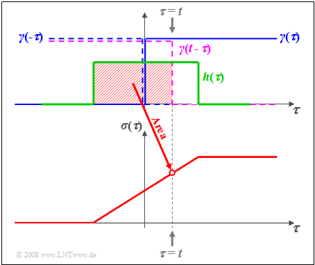
$\text{Beispiel 4:}$ Die Grafik verdeutlicht den Sachverhalt für die Rechteck–Impulsantwort $h(\tau)$.
- Die Abszisse wurde in $\tau$ umbenannt.
- Blau eingezeichnet ist die Sprungfunktion $\gamma(\tau)$.
- Durch Spiegelung und Verschiebung erhält man $\gamma(t - \tau)$ ⇒ violett gestrichelte Kurve.
- Die rot hinterlegte Fläche gibt somit die Sprungantwort $\sigma(\tau)$ zum Zeitpunkt $\tau = t$ an.
Aufgaben zum Kapitel
Aufgabe 1.3: Gemessene Sprungantwort
Aufgabe 1.3Z: Exponentiell abfallende Impulsantwort
Aufgabe 1.4: Zum Tiefpass 2. Ordnung
Aufgabe 1.4Z: Alles rechteckförmig


