Exercise 1.3: Rectangular Functions for Transmitter and Receiver
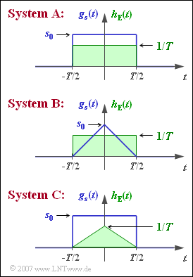
We consider here three variants of a binary bipolar AWGN transmission system which differ with respect to the basic transmission pulse $g_{s}(t)$ as well as the impulse response $h_{\rm E}(t)$ of the receiver filter:
- For $\text{System A}$, both $g_{s}(t)$ and $h_{\rm E}(t)$ are rectangular, only the pulse heights $(s_{\rm 0}$ and $1/T)$ are different.
- $\text{System B}$ differs from $\text{System A}$ by having a triangular-shaped basic transmission pulse with $g_{s}(t=0) = s_{\rm 0}$.
- $\text{System C}$ has the same rectangular basic transmission pulse as $\text{System A}$, while the impulse response is triangular with $h_{\rm E}(t=0) = 1/T$.
The absolute width of the rectangular and triangular functions considered here is $T = 10 \ \rm µ s$ each. The bit rate is $R = 100 \ \rm kbit/s$. The other system parameters are given as follows:
- $$s_0 = 6 \,\,\sqrt{W}\hspace{0.05cm},\hspace{0.3cm} N_{\rm 0} = 2 \cdot 10^{-5} \,\,{\rm W/Hz}\hspace{0.05cm}.$$
Notes:
- The exercise belongs to the chapter "Error Probability for Baseband Transmission".
- You can use the interactive applet "Complementary Gaussian Error Functions" to determine error probabilities.
- Consider "Wiener-Khintchine's theorem" when calculating the detection noise power:
- $$ \sigma _d ^2 = \frac{N_0 }{2} \cdot \int_{ - \infty }^{ + \infty } {\left| {H_{\rm E}( f )} \right|^2 \hspace{0.1cm}{\rm{d}}f} = \frac{N_0 }{2} \cdot \int_{ - \infty }^{ + \infty } {\left| {h_{\rm E}( t )} \right|^2 \hspace{0.1cm}{\rm{d}}t}\hspace{0.05cm}.$$
Questions
Solution
- $$g_d (t = 0) = \int_{ - T/2}^{ + T/2} { g_s(t) \cdot h_{\rm E}( t )} \hspace{0.1cm}{\rm{d}}t =s_0 \cdot \frac{1 }{T} \cdot T = s_0 \hspace{0.1cm}\underline { = 6 \,\,\sqrt{{\rm W}}}\hspace{0.05cm}.$$
There is no intersymbol interfering because for $| t |\ge T$ the detection pulse is $g_{d}(t) = 0$.
2. The variance of the noise component of the detection signal – referred to as the "detection noise power" – can be calculated in both the time and frequency domains.
- For the present rectangular waveform, calculation in the time domain yields faster results:
- $$\sigma _d ^2 \ = \ \frac{N_0 }{2} \cdot \int_{ - \infty }^{ + \infty } {\left| {h_{\rm E}( t )} \right|^2 \hspace{0.1cm}{\rm{d}}t} =\frac{N_0 }{2} \cdot \int_{ - T/2 }^{ + T/2 } {\left| {h_{\rm E}( t )} \right|^2 \hspace{0.1cm}{\rm{d}}t} = \ \frac{N_0 }{2} \cdot\frac{1 }{T^2} \cdot T = \frac{N_0 }{2T} = \frac{2 \cdot 10^{-5} \,\,{\rm W/Hz}}{2 \cdot 10^{-5} \,\,{\rm s}} \hspace{0.1cm}\underline {= 1\,{\rm W}}\hspace{0.05cm}.$$
- The frequency domain calculation would be as follows with $H_{\rm E}(f) = {\rm sinc}(fT)$:
- $$\sigma _d ^2 = \frac{N_0 }{2} \cdot \int_{ - \infty }^{ + \infty } {\left| {H_{\rm E}( f )} \right|^2 \hspace{0.1cm}{\rm{d}}f} = \frac{N_0 }{2} \cdot \int_{- \infty }^{ \infty } {\rm sinc}^2(f T)\hspace{0.1cm}{\rm{d}}f = \frac{N_0 }{2T} \hspace{0.05cm}.$$
3. Due to the time-limited pulse shape (this means: no intersymbol interfering!), the bipolar approach assumed here yields:
- $$p_{\rm B} = {\rm Q} \left( \frac{s_0}{\sigma_d}\right)= {\rm Q} \left( \frac{ 6 \,\sqrt{\rm W}}{1 \,\sqrt{\rm W}}\right) = {\rm Q}(6) \hspace{0.1cm}\underline {= 0.987 \cdot 10^{-9}} \hspace{0.05cm}.$$
- System A represents the matched filter realization of the optimal binary receiver, so the following equations would also be applicable:
- $$E_{\rm B} = s_0^2 \cdot T = 36\, {\rm W} \cdot 10^{-5} {\rm s}\hspace{0.3cm} \Rightarrow \hspace{0.3cm} p_{\rm B} = {\rm Q} \left( \sqrt{\frac{2 \cdot E_{\rm B}}{N_0}}\right) ={\rm Q} \left( \sqrt{\frac{2 \cdot 36 \cdot 10^{-5}\,\, {\rm Ws}}{2 \cdot 10^{-5} \,\, {\rm Ws}}}\right)={\rm Q}(6) \hspace{0.05cm}.$$
4. Since System B uses the same receiver filter as System A, the same detection noise power $σ_{d}^2 = 1 \ \rm W$ is also obtained.
- However, the basic detection pulse is now no longer triangular, but has a more pointed shape. At time $t = 0$ applies:
- $$g_d (t = 0) = \frac{1}{T} \cdot \int_{ - T/2}^{ + T/2} { g_s(t) } \hspace{0.1cm}{\rm{d}}t = \frac{1}{T} \cdot \frac{s_0 }{2} \cdot T = \frac{s_0 }{2}\hspace{0.1cm}\underline {= 3 \,\,\sqrt{\rm W}}\hspace{0.05cm}.$$
- System B is also free of intersymbol interfering. Therefore, one obtains for the bit error probability:
- $$p_{\rm B} = {\rm Q} \left( \frac{g_d (t = 0)}{\sigma_d}\right)= {\rm Q} \left( \frac{ 3 \,\sqrt{\rm W}}{1 \,\sqrt{\rm W}}\right) = {\rm Q}(3) \hspace{0.1cm}\underline {= 0.135 \cdot 10^{-2}} \hspace{0.05cm}.$$
- On the other hand, the following calculation is not applicable here:
- $$E_{\rm B} = \int^{+\infty} _{-\infty} g_s^2(t)\,{\rm d}t = 2\cdot s_0^2 \cdot \int ^{+T/2} _{0} \left( 1- \frac{2t}{T}\right)^2\,{\rm d}t = \frac{s_0^2 \cdot T }{3} = 12 \cdot 10^{-5} \,{\rm Ws}$$
- $$\Rightarrow \hspace{0.3cm} p_{\rm B} = {\rm Q} \left( \sqrt{\frac{2 \cdot E_{\rm B}}{N_0}}\right) ={\rm Q} \left( \sqrt{12}\right)={\rm Q}(3.464) \approx 3 \cdot 10^{-4} \hspace{0.05cm}.$$
- One would thus compute a bit error probability that is too low, since the implicit assumption of a matched filter does not hold.
5. For the rectangular basic transmission pulse and the triangular impulse response ⇒ System C,
the same basic detection pulse is obtained as for the triangular $g_{\rm s}(t)$ and the rectangular $h_{\rm E}(t)$.
- Therefore, as in System B:
- $$g_d (t = 0) = \frac{s_0}{2}\hspace{0.1cm}\underline {= 3 \,\,\sqrt{\rm W}}\hspace{0.05cm}.$$
- In contrast, the detection noise power is now smaller than in systems A and B:
- $$\sigma _d ^2 = \frac{N_0}{2} \cdot \frac{1}{T^2} \cdot \int^{+T/2} _{-T/2} \left( 1- \frac{2t}{T}\right)^2\,{\rm d}t = \frac{N_0}{6T}\hspace{0.1cm}\underline { = 0.333 \,{\rm W}}.$$
- This now gives us for the bit error probability:
- $$p_{\rm B} = {\rm Q} \left( \frac{ 3 \,\sqrt{\rm W}}{0.577 \,\sqrt{\rm W}}\right) \approx {\rm Q}(5.2)\hspace{0.1cm}\underline { \approx 10^{-7} } \hspace{0.05cm}.$$
- The apparent increase in error probability by a factor of about $100$ compared to subtask (3) is due to the severe mismatch compared to the matched filter.
- The improvement over subtask (4) is due to the higher signal energy.
