Exercise 1.3: System Comparison at AWGN Channel
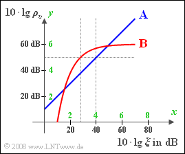
For the comparison of different modulation and demodulation methods with regard to noise sensitivity, we usually assume the so-called AWGN channel and present the following double logarithmic diagram:
- The y-axis indicates the "sink-to-noise ratio" (logarithmic SNR) ⇒ $10 · \lg ρ_v$ in dB.
- $10 · \lg ξ$ is plotted on the x-axis; the normalized power parameter ("performance parameter") is characterized by:
- $$ \xi = \frac{P_{\rm S} \cdot \alpha_{\rm K}^2 }{{N_0} \cdot B_{\rm NF}}\hspace{0.05cm}.$$
- Thus, the transmission power $P_{\rm S}$, the channel attenuation factor $α_{\rm K}$, the noise power density $N_0$ and the bandwidth $B_{\rm NF}$ of the message signal are suitably summarised together in $ξ$.
- Unless explicitly stated otherwise, the following values shall be assumed in the exercise:
- $$P_{\rm S}= 5 \;{\rm kW}\hspace{0.05cm}, \hspace{0.2cm} \alpha_{\rm K} = 0.001\hspace{0.05cm}, \hspace{0.2cm} {N_0} = 10^{-10}\;{\rm W}/{\rm Hz}\hspace{0.05cm}, \hspace{0.2cm} B_{\rm NF}= 5\; {\rm kHz}\hspace{0.05cm}.$$
Two systems are plotted in the graph and their $(x, y)$-curve can be described as follows:
- $\text{System A}$ is characterized by the following equation:
- $$y = x+1.$$
- $\text{System B}$ is instead characterized by:
- $$ y= 6 \cdot \left(1 - {\rm e}^{-x+1} \right)\hspace{0.05cm}.$$
The additional axis labels drawn in green have the following meaning:
- $$ x = \frac{10 \cdot {\rm lg} \hspace{0.1cm}\xi} {10 \,{\rm dB}}\hspace{0.05cm}, \hspace{0.3cm}y = \frac{10 \cdot {\rm lg} \hspace{0.1cm}\rho_v} {10 \,{\rm dB}}\hspace{0.05cm}.$$
- Thus $x = 4$ represents $10 · \lg ξ = 40\text{ dB}$ or $ξ = 10^4$
- and $y = 5$ represents $10 · \lg ρ_v= 50\text{ dB}$ , i.e., $ρ_v = 10^5$.
Hints:
- This exercise belongs to the chapter Quality Criteria.
- Particular reference is made to the page Investigating at the AWGN channel.
- By specifying the powers in watts, they are independent of the reference resistance $R$.
Questions
Solution
- $$\xi = \frac{5 \cdot 10^3\,{\rm W}\cdot 10^{-6} }{10^{-10}\,{\rm W}/{\rm Hz} \cdot 5 \cdot 10^3\,{\rm Hz}} = 10^4 \hspace{0.3cm} \Rightarrow \hspace{0.3cm} 10 \cdot {\rm lg} \hspace{0.1cm}\xi = 40\,{\rm dB} \hspace{0.3cm} \Rightarrow \hspace{0.3cm} x=4 \hspace{0.05cm}.$$
- This gives the auxiliary coordinate value $y = 5$, which leads to a sink SNR of $10 · \lg \hspace{0.05cm} ρ_v\hspace{0.15cm}\underline{ = 50 \ \rm dB}$.
(2) Answers 2 and 3 are correct:
This requirement corresponds to a $10$ dB increase in the sink SNR compared to the previous system, so $10 · \lg \hspace{0.05cm}ξ$ must also be increased by $10$ dB:
- $$10 \cdot {\rm lg} \hspace{0.1cm}\xi = 50\,{\rm dB} \hspace{0.3cm} \Rightarrow \hspace{0.3cm} \xi=10^5 \hspace{0.05cm}.$$
A tenfold larger $ξ$ value is achieved (provided all other parameters are held constant in each case)
- by a transmission power of $P_{\rm S} = 50$ kW instead of $5$ kW,
- by a channel transmission factor of $α_{\rm K} = 0.00316$ instead of $0.001$,
- by a noise power density of $N_0 = 10^{ –11 }$ W/Hz instead of $10^{ –10 }$ W/Hz,
- by a signal bandwidth of $B_{\rm NF} = 0.5$ kHz instead of $5$ kHz.
(3) For $10 · \lg \hspace{0.05cm} ξ = 40$ dB, the auxiliary value is $x = 4$. This gives the auxiliary $y$–value:
- $$y= 6 \cdot \left(1 - {\rm e}^{-3} \right)\approx 5.7 \hspace{0.05cm}.$$
- This corresponds to a sink SNR of $10 · \lg \hspace{0.05cm} ρ_v\hspace{0.15cm}\underline{ = 57 \ \rm dB}$ ⇒ $7$ dB improvement over $\text{System A}$.
(4) This problem is described by the following equation:
- $$ y= 6 \cdot \left(1 - {\rm e}^{-x+1} \right) = 5 \hspace{0.3cm} \Rightarrow \hspace{0.3cm} {\rm e}^{-x+1} ={1}/{6}\hspace{0.3cm} \Rightarrow \hspace{0.3cm} x = 1+ {\rm ln} \hspace{0.1cm}6 \approx 2.79 \hspace{0.3cm} \Rightarrow \hspace{0.3cm} 10 \cdot {\rm lg} \hspace{0.1cm}\xi = 27.9\,{\rm dB}\hspace{0.05cm}.$$
- For $\text{System A}$ $10 · \lg \hspace{0.05cm} \xi = 40$ dB is required, which was achieved with $P_{\rm S} = 5$ kW and the other numerical values given.
- Now the transmission power can be reduced by about $12.1$ dB:
- $$ 10 \cdot {\rm lg} \hspace{0.1cm} \frac{P_{\rm S}}{ 5 \;{\rm kW}}= -12.1\,{\rm dB} \hspace{0.3cm} \Rightarrow \hspace{0.3cm} \frac{P_{\rm S}}{ 5 \;{\rm kW}} = 10^{-1.21}\approx 0.06\hspace{0.05cm}.$$
- This means that in $\text{System B}$ the same system quality is achieved with only $6\%$ of the transmission power of $\text{System A}$ – i.e., with only $P_{\rm S} \hspace{0.15cm}\underline{ = 0.3 \ \rm kW}$.
(5) The larger sink SNR of $\text{System B}$ compared to $\text{System A}$ we will denote with $V$ (from German "Verbesserung" ⇒ "improvement"):
- $$V = 10 \cdot {\rm lg} \hspace{0.1cm}\rho_v \hspace{0.1cm}{\rm (System\;B)} - 10 \cdot {\rm lg} \hspace{0.1cm}\rho_v \hspace{0.1cm}{\rm (System\;A)} = \left[6 \cdot \left(1 - {\rm e}^{-x+1} \right) -x -1 \right] \cdot 10\,{\rm dB}\hspace{0.05cm}.$$
- Setting the derivative to zero yields the $x$–value that leads to the maximum improvement:
- $$ \frac{{\rm d}V}{{\rm d}x} = 6 \cdot {\rm e}^{-x+1} -1\Rightarrow \hspace{0.3cm} x = 1+ {\rm ln} \hspace{0.1cm}6 \hspace{0.3cm} \Rightarrow \hspace{0.3cm} 10 \cdot {\rm lg} \hspace{0.1cm}\xi = \hspace{0.15cm}\underline {27.9\,{\rm dB}}\hspace{0.05cm}.$$
- This results in exactly the case discussed in subtask (4) with $10 · \lg ρ_υ = 50$ dB, while the sink SNR for $\text{System A}$ is only $37.9$ dB.
- The improvement is therefore $12.1$ dB.
