Exercise 2.2Z: Distortion Power again
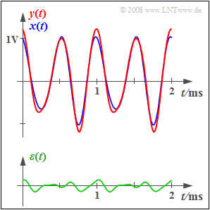
At the input of the considered functional unit, which is not specified in more detail, there is the periodic signal $x(t)$ shown in blue in the graph. This is given by the spectrum of the corresponding analytical signal:
- $$X_+(f) = {1 \,\rm V} \cdot {\rm \delta}(f- {2 \,\rm kHz}) + {0.2 \,\rm V} \cdot {\rm e}^{\rm j \hspace{0.05cm}\cdot \hspace{0.05cm}90^{\circ} } \cdot \delta(f- {3 \,\rm kHz}).$$
This spectral function is obtained from the usual spectrum $X(f)$, by
- truncating all components at negative frequencies, and
- doubling the components at positive frequencies.
For more details on the analytical signal and its spectrum, see the chapter Analytical Signal and its Spectral Function of the book "Signal Representation".
The spectrum of the analytical signal at the output of the functional unit is:
- $$Y_+(f) = {1.1 \,\rm V} \cdot {\rm \delta}(f- {2 \,\rm kHz}) + {0.25 \,\rm V} \cdot {\rm e}^{\rm j \hspace{0.05cm}\cdot \hspace{0.05cm} 60^{\circ} } \cdot \delta(f- {3 \,\rm kHz})+ {0.05 \,\rm V} \cdot {\rm e}^{-\rm j \hspace{0.05cm}\cdot \hspace{0.05cm} 90^{\circ} } \cdot \delta(f- {5 \,\rm kHz}).$$
The bottom sketch shows the difference signal $\varepsilon(t) = y(t) - x(t)$. A measure of the distortion created in the system is the "distortion power" referenced to the resistance $R = 1 \ \rm \Omega$ .
- $$P_{\rm V} = \overline{\varepsilon^2(t)} = \frac{1}{T_{\rm 0}} \cdot \int_{0}^{ T_{\rm 0}} {\varepsilon^2(t) }\hspace{0.1cm}{\rm d}t.$$
It should be noted that the distortion power can also be calculated in the spectral domain – in fact, in a simpler way here.
The power $P_x$ of the input signal $x(t)$ is defined in an analogous way. As a quantitative measure of the strength of the distortions the signal–to–distortion–power ratio is specified, which is usually expressed logarithmically (in dB):
- $$10 \cdot {\rm lg} \hspace{0.1cm}\rho_{\rm V} = 10 \cdot {\rm lg} \hspace{0.1cm}{ P_{x}}/{P_{\rm V}} \hspace{0.05cm}.$$
Please note:
- The exercise belongs to the chapter Classification of the Distortions.
- All powers queried here refer to the resistance $R = 1 \ \rm \Omega$ and thus have the unit ${\rm V}^2$.
- The power of a (real) signal $x(t)$ can also be computed using the spectral function $X(f)$ :
- $$P_{x} =\frac{1}{T_{\rm 0}} \cdot\int_{-\infty}^{ \infty} x^2(t)\hspace{0.1cm}{\rm d}t = \frac{1}{T_{\rm 0}} \cdot \int_{-\infty}^{ \infty} |X(f)|^2\hspace{0.1cm}{\rm d}f.$$
Questions
Solution
- The greatest common divisor of $f_1 = 2 \ \rm kHz$ and $f_2 = 3 \ \rm kHz$ is $f_0 = 1 \ \rm kHz$.
- Hence, the period is $T_0 = 1/f_0 = 1 \ \rm ms$.
- Due to the phase term ${\rm e}^{{\rm j} \hspace{0.05cm}\cdot \hspace{0.05cm}90^\circ}$ the signal is:
- $$x(t) = {1 \, \rm V} \cdot {\rm cos}(2\pi f_1 t ) - {0.2 \, \rm V} \cdot {\rm sin}(2\pi f_2 t ).$$
(2) To compute the power in the time domain the signal $x(t) = x_1(t) + x_2(t)$ must be squared and averaged over a suitable time interval.
- Averaging over $T_0$ is sufficient for a periodic signal:
- $$P_{\rm V} = \frac{1}{T_{\rm 0}} \cdot \int_{0}^{ T_{\rm 0}} {\left[x_1(t)+ x_2(t) \right]^2 }\hspace{0.1cm}{\rm d}t = \frac{1}{T_{\rm 0}} \cdot \int_{0}^{ T_{\rm 0}} {x_1^2(t) }\hspace{0.1cm}{\rm d}t \hspace{0.1cm}+\hspace{0.1cm} \frac{1}{T_{\rm 0}} \cdot \int_{0}^{ T_{\rm 0}} {x_2^2(t) }\hspace{0.1cm}{\rm d}t \hspace{0.1cm}+\hspace{0.1cm} \frac{2}{T_{\rm 0}} \cdot \int_{0}^{ T_{\rm 0}} { x_1(t) \cdot x_2(t) }\hspace{0.1cm}{\rm d}t.$$
- The first integral yields:
- $$P_{\rm 1} = \frac{1}{T_{\rm 0}} \cdot \int_{0}^{ T_{\rm 0}} { ({1 \, \rm V})^2 \cdot {\rm cos}^2(2\pi f_1 t )}\hspace{0.1cm}{\rm d}t = \frac{1 \, \rm V^2}{2 T_{\rm 0}}\hspace{0.05cm} \cdot \int\limits_{0}^{ T_{\rm 0}} { \left[ 1+ {\rm cos}(4\pi f_1 t )\right]}\hspace{0.1cm}{\rm d}t = {0.5 \, \rm V^2}.$$
- In the same way, the following is obtained for the power of the second term: $P_2 = (0.2 \ {\rm V})^2/2 = 0.02 \ {\rm V}^2.$
- The last integral vanishes since $x_1(t)$ and $x_2(t)$ are orthogonal to each other. Consequently, the following is obtained for the total signal power:
- $$P_{x} =P_{\rm 1} + P_{\rm 2} = {0.5 \, \rm V^2} + {0.02 \, \rm V^2}\hspace{0.15cm}\underline{ = {0.52 \, \rm V^2}}.$$
This result can also be derived from the spectral function by squaring, halving, and summarising the amplitudes of all discrete spectral components. The phase positions of the individual spectral lines do not need to be considered.
(3) Regardless of whether a linear or a non-linear system is at hand the following can be formulated for the analytical spectrum of the difference signal $\varepsilon(t) = y(t) - x(t)$ with $f_2 = 2 \ \rm kHz$, $f_3 = 3 \ \rm kHz$ and $f_5 = 5 \ \rm kHz$ :
- $$E_+(f) = Y_+(f) - X_+(f) = {0.1 \,\rm V} \cdot {\rm \delta}(f- f_2) + \left[{0.25 \,\rm V} \cdot {\rm e}^{\rm j \cdot 60^{\circ} } - {0.2 \,\rm V} \cdot {\rm e}^{\rm j \cdot 90^{\circ} } \right] \cdot \delta(f- f_3) + {0.05 \,\rm V} \cdot {\rm e}^{-\rm j \cdot 90^{\circ} } \cdot \delta(f- f_5).$$
- The complex amplitude of the second term is:
- $$C_2 = {0.25 \,\rm V} \cdot \cos( 60^{\circ}) + {\rm j} \cdot{0.25 \,\rm V} \cdot \sin( 60^{\circ}) - {\rm j} \cdot{0.05 \,\rm V} $$
- $$\Rightarrow \hspace{0.3cm} C_2 = {0.25 \,\rm V} \cdot 0.5 + {\rm j} \cdot{0.25 \,\rm V} \cdot 0.866 - {\rm j} \cdot{0.2 \,\rm V} = {0.125 \,\rm V} + {\rm j} \cdot{0.016 \,\rm V}.$$
- This results in the following for the magnitude:
- $$|C_2| = \sqrt{({0.125 \,\rm V})^2+({0.016 \,\rm V})^2 }= {0.126 \,\rm V}.$$
- The phase positions do not need to be considered in the computation of the power. Thus:
- $$P_{\rm V} = \frac{1}{2} \cdot \left[ ({0.1 \,\rm V})^2 + ({0.126 \,\rm V})^2 + ({0.05 \,\rm V})^2\right] \hspace{0.15cm}\underline{= {0.0142 \, \rm V^2}}.$$
(4) According to the definition on the information page the following holds:
- $$\rho_{\rm V} = \frac{ P_{x}}{P_{\rm V}}= \frac{ {0.52 \, \rm V^2}}{0.0142 \, \rm V^2}\hspace{0.05cm}\rm = 36.65\hspace{0.3cm} \Rightarrow \hspace{0.3cm} 10 \cdot {\rm lg}\hspace{0.1cm}\rho_{\rm V} \hspace{0.15cm}\underline{= {15.64 \, \rm dB}}.$$
