Exercise 3.3Z: High- and Low-Pass Filters in p-Form
From LNTwww
(Redirected from Exercise 3.3Z: High- and Low-Passes in p-Form)
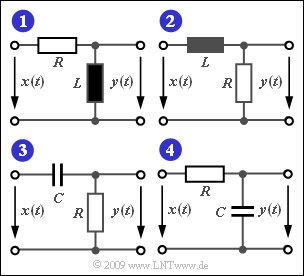
The diagram shows four simple filter configurations with low-pass or high-pass characteristics, which are composed of discrete components.
The following holds for the components of the circuits $(1)$ and $(2)$:
- $$R = 100\,{\rm \Omega}\hspace{0.05cm},\hspace{0.2cm} L = 10\,{\rm µ H}\hspace{0.05cm}.$$
- The four-terminal networks $(1)$, ... , $(4)$ should be characterized by their $p$–transfer functions $H_{\rm L}(p)$ .
- From this (in this task, not in general), the frequency response is obtained according to the equation
- $$H(f) = H_{\rm L}(p)\Bigg |_{\hspace{0.1cm} p\hspace{0.05cm}=\hspace{0.05cm}{\rm j \hspace{0.05cm}2\pi \it f}} \hspace{0.05cm}.$$
Please note:
- The exercise belongs to the chapter Laplace Transform and p-Transfer Function.
Questions
Solution
(1) Both statements are true:
- The following limits hold for the two two-port networks:
- $$\lim_{p \hspace{0.05cm}\rightarrow \hspace{0.05cm}0} H_{\rm TP}(p)\hspace{0.2cm} = \hspace{0.1cm}\lim_{p \hspace{0.05cm}\rightarrow \hspace{0.05cm}0}\frac{K}{p + p_{\rm x}} \hspace{0.15cm} { =K /{p_{\rm x}}}, \hspace{1.2cm} \lim_{p \hspace{0.05cm}\rightarrow \hspace{0.05cm}\infty} H_{\rm TP}(p)= 0\hspace{0.05cm},$$
- $$ \lim_{p \hspace{0.05cm}\rightarrow \hspace{0.05cm}0}H_{\rm HP}(p) \hspace{0.2cm} = \hspace{0.1cm}0, \hspace{1.4cm} \lim_{p \hspace{0.05cm}\rightarrow \hspace{0.05cm}\infty} H_{\rm HP}(p)= \lim_{p \hspace{0.05cm}\rightarrow \hspace{0.05cm}\infty}\frac{K\cdot p}{p + p_{\rm x}} = K \hspace{0.05cm}.$$
- It can be seen that $H_{\rm TP}(p)$ yields zero for very high frequencies and $H_{\rm HP}(p)$ for very low frequencies.
(2) We consider two-port network $(1)$.
- The voltage divider principle leads to the result
- $$H_{\rm L}(p)= \frac { p L} {R + pL}= \frac { p } {p +{R}/{L}} \hspace{0.05cm} .$$
- It is a $\rm high–pass\:filter$ with the characteristic parameter $\underline {K = 1}$ and the zero at
- $$p_{\rm x}= -\frac{R}{L}= -\frac{100\,{\rm \Omega}}{10^{-5 }\,{\rm \Omega s}}\hspace{0.15cm}\underline{= -0.1} \cdot10^{-6 }\,{1}/{\rm s} \hspace{0.05cm} .$$
(3) The transfer function is obtained by using the substitution $p = {\rm j} \cdot 2 \pi f$:
- $$H(f)= \frac { {\rm j} \cdot 2\pi \hspace{-0.05cm}f } {{\rm j} \cdot 2\pi \hspace{-0.05cm}f +p_{\rm x}}\Rightarrow \hspace{0.3cm}\hspace{0.3cm} |H(f)|^2 = \frac { (2\pi \hspace{-0.05cm}f)^2 } {(2\pi \hspace{-0.05cm}f)^2 +p_{\rm x}^2}\hspace{0.05cm} .$$
- The following conditional equation is obtained from the condition $|H(f_{\rm G})|^2 = 0.5 $ :
- $$(2\pi \hspace{-0.05cm}f_{\rm G})^2 = p_{\rm x}^2 \hspace{0.3cm}\Rightarrow \hspace{0.3cm}\hspace{0.3cm} f_{\rm G} = -\frac { p_{\rm x}} {2 \pi}= \frac { 10^{-7 }\, 1/s} {2 \pi}\hspace{0.15cm}\underline{\approx 1.59\,{\rm MHz}}\hspace{0.05cm} .$$
(4) The first statement is correct:
- For a direct $\rm (DC)$ signal, a capacitance $C$ is an infinite resistance. For high frequencies, $C$ acts like a short circuit.
- From this it follows: The two-port network $(3)$ also describes a high-pass filter. In contrast, the circuits $(2)$ and $(4)$ exhibit low-pass filter behaviour.
(5) The $p$–transfer function of two-port network $(3)$ is:
- $$H_{\rm L}(p)= \frac { R } {{1}/{(pC)} + R}= \frac { p } {p +{1}/{(RC)}}\hspace{0.3cm} \Rightarrow \hspace{0.3cm}p_{\rm x}= -{1}/(RC)\hspace{0.3cm}\Rightarrow \hspace{0.3cm} C = -\frac{1}{p_{\rm x} \cdot R}= \frac{-1}{-10^{-7 }\, 1/s \cdot 100\,{\rm \Omega}}\hspace{0.15cm}\underline{ = 1\,{\rm nF}} \hspace{0.05cm} .$$
