Exercise 3.4Z: Various All-Pass Filters
We first assume a two-port network with the following transfer function:
- $$H_{\rm L}(p)= \frac {1-{p}/{A}} {1+{p}/{A}}.$$
From this is to be determined the conventional Fourier frequency response
- $$H(f) = {\rm e}^{-a(f)\hspace{0.05cm}}\cdot {\rm e}^{- \hspace{0.05cm}{\rm j} \hspace{0.05cm}\cdot \hspace{0.05cm}b(f)},$$
which is representable
- by the attenuation function $a(f)$
- and the phase function $b(f)$.
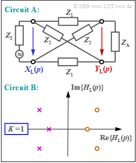
The upper diagram shows a so-called "all-pass circuit" where the complex resistance $Z_1$ denotes an inductance and the complex resistance $Z_2$ denotes a capacitance:
- $$Z_1 = p \cdot L\hspace{0.05cm},\hspace{0.2cm}Z_2 = \frac{1}{p \cdot C}\hspace{0.05cm}.$$
For reflection-free adaptation at the input and output with
- $$Z_{\rm I}=Z_{\rm A} = \sqrt{Z_1 \cdot Z_2} = \sqrt{{L}/{C}},$$
the following holds for the $p$–transfer function of circuit $\rm A$ (see upper diagram):
- $$H_{\rm L}(p)= \frac {Y_{\rm L}(p)} {X_{\rm L}(p)}= \frac {Z_2-Z_1} {Z_1+2 \cdot \sqrt{Z_1 \cdot Z_2}+Z_2}\hspace{0.05cm}.$$
Circuit $\rm B$ is defined by the pole–zero diagram of the $p$–transfer function. It is characterized by the fact that
- all poles (in the left $p$–half-plane)
- are located in a mirror-imaged manner with respect to the zeros (in the right half-plane).
Please note:
- The exercise belongs to the chapter Laplace Transform and p-Transfer Function.
Questions
Solution
- $$H_{\rm L}(p)= \frac {1-{p}/{A}} {1+{p}/{A}}= -1 \cdot \frac {p-A} {p+A}\hspace{0.3cm}\Rightarrow \hspace{0.3cm}\hspace{0.15cm} \underline{K =- 1}, \hspace{0,2cm} \hspace{0.15cm} \underline{p_{\rm o}/A = 1} ,\hspace{0,2cm} \hspace{0.15cm} \underline{ p_{\rm x}/A = -1} \hspace{0.05cm} .$$
(2) Statements 2 and 3 are correct:
- If $p = {\rm j} \cdot 2 \pi f$ is set, the following is obtained:
- $$H(f)= \frac {1-{\rm j \cdot 2\pi \it f}/A} {1+{\rm j \cdot 2\pi \it f}/A}\hspace{0.05cm} .$$
- The magnitude of a quotient is equal to the quotient of the magnitudes:
- $$|H(f)|= \frac {|1-{{\rm j} \cdot 2\pi f}/A|} {|1+{\rm j \cdot 2\pi \it f}/A|}= \frac {\sqrt{1+(2\pi f/A)^2}} {\sqrt{1+(2\pi f/A)^2}}= 1\hspace{0.3cm} \Rightarrow \hspace{0.3cm} a(f)= -{\rm ln} \hspace{0.1cm} |H(f)|= 0\hspace{0.2cm}({\rm Np \hspace{0.2cm}or \hspace{0.2cm}dB})\hspace{0.05cm} .$$
- However, $\text{statement 3}$ is also correct as can be seen from the theory page "Graphical determination of attenuation".
(3) The phase function $b(f)$ can be computed as follows:
- $$b(f)= -{\rm arc} \hspace{0.1cm} H(f) \hspace{0.25cm} = \hspace{0.2cm} {\rm arctan } \hspace{0.1cm} ({2\pi f}/{A}) - {\rm arctan } \hspace{0.1cm} ({-2\pi f}/{A}) = 2 \cdot {\rm arctan } \hspace{0.1cm} ({2\pi f}/{A}),$$
- $$b(f= {A}/{2\pi})= 2 \cdot {\rm arctan } \hspace{0.1cm}(1) = 2 \cdot 45^\circ \hspace{0.15cm} \underline{ = 90^\circ}\hspace{0.05cm},$$
- $$ b(f= {A}/{\pi})=2 \cdot {\rm arctan } \hspace{0.1cm}(2) = 2 \cdot 63.4^\circ \hspace{0.15cm} \underline{= 126.8^\circ}\hspace{0.05cm} ,$$
- $$ b(f \rightarrow \infty)=2 \cdot {\rm arctan } \hspace{0.1cm}(\infty) = 2 \cdot 90^\circ \hspace{0.15cm} \underline{= 180^\circ}\hspace{0.05cm} .$$
- The same results are obtained following the approach according to the page "Graphical determination of phase" in the theory part.
(4) Only statement 1 is correct:
- The given $p$–transfer function can be expressed as follows:
- $$H_{\rm L}(p)= \frac {Z_2-Z_1} {Z_1+2 \cdot \sqrt{Z_1 \cdot Z_2}+Z_2}= \frac {(\sqrt{Z_2}-\sqrt{Z_1})(\sqrt{Z_2}+\sqrt{Z_1})} {(\sqrt{Z_2}+\sqrt{Z_1})^2}= \frac {\sqrt{Z_2}-\sqrt{Z_1}} {\sqrt{Z_2}+\sqrt{Z_1}}\hspace{0.05cm}.$$
- Furthermore, considering $Z_1 = p \cdot L$ and $Z_2 = 1/(p \cdot C)$ the following is obtained:
- $$H_{\rm L}(p)= \frac {\sqrt{{1}/(pC)}-\sqrt{pL}} {\sqrt{{1}/(pC)}+\sqrt{pL}} = \frac {1- p \cdot \sqrt{LC}} {1+ p \cdot \sqrt{LC}} = -1 \cdot \frac {p-\sqrt{{1}/(LC)}} {p+\sqrt{{1}/(LC)}}\hspace{0.3cm} \Rightarrow \hspace{0.3cm}A = \sqrt{{1}/(LC)}: \hspace{0.2cm}H_{\rm L}(p)= -1 \cdot \frac {p-A} {p+A}\hspace{0.05cm}.$$
- The same transfer function as computed in subtask (1) is obtained.
From this it follows that only statement 1 is correct:
- The attenuation curve is $a(f) = 0\ \rm (Np)$. No frequency is attenuated or amplified. Therefore, it is called an "all-pass filter".
- The second statement is false. The phase response $b(f)$ is not linear but rather curved as computed in subtask (3) .
- The Hilbert transform of the constant $a(f) = 0$ should result in the phase function $b(f) = 0$ as shown in the theory part. That is: statement 3 is false.
- The attenuation function $a(f)$ and phase function $b(f)$ are related to each other via the Hilbert transformation only for minimum-phase systems.
- However, in such a minimum–phase system, all poles and zeros lie in the left $p$–half-plane which is not true here
⇒ an all-pass filter is not a minimum–phase system.
(5) Both statements are correct:
- As already determined in subtask (2): A constant attenuation arises as a result whenever there is a corresponding zero in the right half-plane for each pole in the left $p$–half-plane ⇒ circuit $\rm B$ also exhibits all-pass filter charakteristics.
- Since $b(f)$ is always an asymmetric function, $b(f= 0) = 0$ holds in general. That is, for any spectral function $H(f)$ whose inverse Fourier transform ("impulse response") is real.
