Difference between revisions of "Mobile Communications/Characteristics of UMTS"
m (Text replacement - "[[Modulationsverfahren" to "[[Modulation_Methods") |
|||
| Line 6: | Line 6: | ||
}} | }} | ||
| − | == | + | == Requirements for third generation mobile radio systems == |
<br> | <br> | ||
| − | + | The main motivation for the development of '''Third generation mobile radio systems'' was the realization that 2G–systems could not satisfy the bandwidth requirements for the use of multimedia services. | |
| − | [[File:EN_Mob_T_3_4_S1.png|right|frame| | + | [[File:EN_Mob_T_3_4_S1.png|right|frame|Development of the mobile radio systems|class=fit]] |
| − | + | The graph shows the development of mobile radio systems from 1995 to 2006 in terms of performance. The specified data rates were still realistic for 2011 with no more than two active users in one cell. The maximum values often stated by providers were mostly not reached in practice. | |
| − | + | Third-generation mobile communications systems should have a greater bandwidth and sufficient reserve capacity to ensure a high quality of service (QoS) even with growing requirements. | |
| − | + | Prior to the development of the 3G–systems, the <i>International Telecommunication Union</i> (ITU) created a catalog of requirements which includes the following general conditions: | |
| − | * | + | *High data rates from $\text{144 kbit/s}$ (Standard) to $\text{2 Mbit/s}$ (In-door),<br> |
| − | * | + | *symmetric and asymmetric data transmission (IP–services),<br> |
| − | * | + | *high speech quality and high spectral efficiency, |
| − | * | + | *global accessibility and distribution,<br> |
| − | * | + | *seamless transition from and to second generation systems,<br> |
| − | * | + | *Applicability independent of the network used (<i>Virtual Home Environment</i> ), |
| − | * | + | *Provision of circuit-switched and packet-switched transmission.<br><br> |
| − | + | During the introduction of UMTS (<i><b>U</b>niversal <b>M</b>obile <b>T</b>elecommunication <b>S</b>ystem</i>) as the best known 3G–standard, the expansion and diversification of the services offered was a decisive motive. A UMTS–capable terminal device must support a number of complex and multimedia applications in addition to the classic services (voice transmission, messaging, etc.), including >br> | |
| − | * | + | *with regard to ''Information:'' Internet surfing (Info–on–demand), online print media,<br> |
| − | * | + | *regarding ''Communication:'' video and audio conference, fax, ISDN, messaging,<br> |
| − | * | + | *regarding ''Entertainment:'' Mobile TV, Video–on–Demand, Online–Gaming,<br> |
| − | * | + | *in the ''business area:'' Interactive shopping, E–Commerce,<br> |
| − | * | + | *in the ''technical area:'' Online–support, distribution service (language and data),<br> |
| − | * | + | *in the ''medical field:'' telemedicine.<br><br> |
| − | == | + | *** Translated with www.DeepL.com/Translator (free version) *** |
| + | |||
| + | |||
| + | == The IMT-2000 standard == | ||
<br> | <br> | ||
| − | + | Around 1990, the <i>International Telecommuncation Union</i> (ITU) created the '''Standard IMT-2000''' (<i>'''I'''nternational '''M'''obile '''T'''elecommunications at the year</i> '''2000'''), which was to make the above-mentioned requirements possible. IMT–2000 comprises a number of third-generation mobile communications systems that have been brought closer together in the course of standardization to enable the development of common terminals for all these standards.<br> | |
| − | + | In order to take into account different preliminary work and to give network operators the possibility to continue to use existing network architectures in part, IMT–2000 contains several individual standards. These can be roughly divided into four categories: | |
| − | [[File:P ID2208 Mob T 3 4 S2 v1.png|right|frame| | + | [[File:P ID2208 Mob T 3 4 S2 v1.png|right|frame|The IMT Family|class=fit]] |
| − | *<b>W–CDMA:</b> | + | *<b>W–CDMA:</b> This includes the FDD component of the European UMTS–standard and the American cdma2000–system. |
| − | *<b> | + | *<b>CDMA:</b> This group includes the TDD–component of UMTS as well as the Chinese TD–SCDMA.<br> integrated in it. |
| − | *<b>TDMA:</b> | + | *<b>TDMA:</b> A further development of the GSM–derived EDGE and its American counterpart UWC–136, also known as D–AMPS.<br> |
| − | *<b>FD–TDMA:</b> | + | *<b>FD–TDMA:</b>nbsp; further development of the European cordless–telephony–DECT standard (<i>Digital Enhanced Cordless Telecommunication</i>).<br> |
<br clear=all> | <br clear=all> | ||
| − | + | We concentrate here on the mobile communications system UMTS developed in Europe, which supports the two standards W–CDMA and TD–CDMA of the system family IMT–2000, under the following designations: | |
| − | *<b>UTRA–FDD</b> ⇒ ''UMTS Terrestrial Radio Access – Frequency Division Duplex'': | + | *<b>UTRA–FDD</b> ⇒ ''UMTS Terrestrial Radio Access – Frequency Division Duplex'': <br>This consists of twelve paired uplink and downlink frequency bands each $\text{5 MHz}$ bandwidth. In Europe these are between $\text{1920}$ and $\text{1980 MHz}$ in the uplink and between $\text{2110}$ and $\text{2170 MHz}$ in the downlink. In the summer of 2000, the auction of the licenses for Germany with a 20-year term brought in approx. 50 billion Euro.<br> |
| − | *<b>UTRA–TDD</b> ⇒ ''UMTS Terrestrial Radio Access – Time Division Duplex'': | + | *<b>UTRA–TDD</b> ⇒ ''UMTS Terrestrial Radio Access – Time Division Duplex'': <br>Here, five bands of $\text{5 MHz}$ bandwidth are provided in which both uplink and downlink data are to be transmitted by means of time division multiplexing. For UTRA–TDD the frequencies between $\text{1900}$ and $\text{1920 MHz}$ (four channels) and between $\text{202020}$ and $\text{2025 MHz}$ (one channel) are reserved.<br> |
| − | == | + | *** Translated with www.DeepL.com/Translator (free version) *** |
| + | |||
| + | |||
| + | == System architecture and basic units for UMTS == | ||
<br> | <br> | ||
| − | + | The network–architecture of UMTS can be divided into two main blocks.<br> | |
| + | |||
| + | The ''UMTS Terrestrial Radio Access Network'' (<b>UTRAN</b>) ensures the wireless transmission of data between the transport level and the radio network level. This includes the base stations and the control nodes, whose functions are described below: | ||
| + | *A UMTS–base station is, also called <b>Node B</b> , comprises the antenna system and the CDMA–receiver and is directly connected to the radio interfaces of all users in the cell. The tasks of a "Node B" include data rate matching, data and channel (de)coding, interleaving, and modulation or demodulation. Each base station can serve one or more cells (sectors).<br> | ||
| − | + | *The <b>Radio Network Controller</b> (RNC) is responsible for controlling the base stations. It is also responsible within the cells for call acceptance control, encryption and decryption, conversion to ATM (<i>Asynchronous Tranfer Mode</i>), channel assignment, handover and power control.<br><br> | |
| − | |||
| − | + | The ''Core Network'' (<b>CN</b>) takes over the switching of the data within the UMTS–network. For this purpose, it contains the following hardware and software components at <i> circuit switching</i> : | |
| + | *The <b>Mobile Switching Center</b> (MSC) is responsible for localization/authentication, routing of calls, handover and encryption of user data.<br> | ||
| − | + | *The <b>Gateway Mobile Switching Center</b> (GMSC) organizes the connection to other networks, for example to the landline network.<br> | |
| − | * | ||
| − | * | + | *<b>MSC</b> and <b>GMSC</b> have access to various databases like [[Examples_of_Communication_Systems/Allgemeine_Beschreibung_von_GSM#Switching_and_Management_Subsystem_.28SMSS.29| ''' checkLink:_Buch_9 ⇒ ''' |
| + | Home Location Register]] (HLR) and [[Examples_of_Communication_Systems/Allgemeine_Beschreibung_von_GSM#Switching_and_Management_Subsystem_.28SMSS.29| ''' checkLink:_Buch_9 ⇒ ''' Visitor Location Register]] (VLR).<br> | ||
| − | + | [[File:P ID2209 Mob T 3 4 S3 v1.png|right|frame|UMTS-access level (with line switching)|class=fit]] | |
| + | <The diagram shows the UMTS–architecture for circuit switching ( <i>Circuit Switching</i> ), where the <i>Core Network</i> (CN) is organized similar to the GSM–architecture. | ||
| − | [[ | + | The [[Examples_of_Communication_Systems/UMTS%E2%80%93Netzarchitektur#Architektur_der_Zugangsebene|''' checkLink:_Buch_9 ⇒ ''' System Architecture for Packet Switching]] (english: <i>Packet Switching</i> ) differs fundamentally from this: |
| − | |||
| − | + | *Here, the communication partners do not use the channel assigned to them exclusively, but the packets are mixed with those of other users. | |
| + | *One finds there similar components as with the GSM–Extension [[Examples_of_Communication_Systems/Weiterentwicklungen_des_GSM#General_Packet_Radio_Service_.28GPRS.29| ''' checkLink:_Buch_9 ⇒ ''' General Packet Radio Service]] (GPRS).<br clear=all> | ||
| − | |||
| − | |||
| − | == CDMA | + | == CDMA - Multiple access with UMTS == |
<br> | <br> | ||
| − | UMTS | + | UMTS uses the multiple access method [[Modulation_Methods/PN%E2%80%93Modulation#Blockschaltbild_und_.C3.A4quivalentes_Tiefpass.E2.80.93Modell| ''' checkLink:_Buch_5 ⇒ ''' ''Direct Sequence Code Division Multiple Access'']] ('''DS–CDMA'''). The procedure is sometimes also called "PN–Modulation".<br> |
| − | [[File:EN Mob T 3 4 S4.png|center|frame| | + | [[File:EN Mob T 3 4 S4.png|center|frame|Principle and signal characteristics with "DS-CDMA" for two users|class=fit]] |
| − | + | The diagram shows the principle using a simplified model and exemplary signals for the "user 1". For simplification the noise signal $n(t) \equiv 0$ is set for the displayed signals. It is valid: | |
| − | * | + | *The two source signals $q_1(t)$ and $q_2(t)$ use the same AWGN–channel without interfering with each other. The bit duration of each data signal is $T_{\rm B}$.<br>. |
| − | * | + | *Each of the data signals is multiplied by an assigned spreading code, $c_1(t)$ or $c_2(t)$ . The sum signal is transmitted; |
| − | :$$s(t) = s_1(t) + s_2(t) = | + | :$$s(t) = s_1(t) + s_2(t) = q_1(t) \cdot c_1(t) + q_2(t) \cdot c_2(t).$$ |
| − | * | + | *The bandwidths of the partial signals $s_1(t)$ and $s_2(t)$ as well as of the resulting transmitedt signal $s(t)$ are larger than the bandwidths of $q_1(t)$ and $q_2(t)$ by the '''spreading factor'' $ J = T_{\rm C}/T_{\rm B}$ . For the graphic $J = 4$ was chosen. |
| − | * | + | *The same spreading codes $c_1(t)$ or $c_2(t)$ are added multiplicatively to the receiver. In the case of orthogonal codes and small AWGN–noise $n(t)$ the data signals can then be separated again. This means that $v_1(t) = q_1(t)$ and $v_2(t) = q_2(t)$.<br> |
| − | * | + | *If AWGN–noise is present, the digital output signals are different from the input signals, but the probability of error is not increased by the other users as long as the used spreading sequences are orthogonal.<br> |
| − | * | + | *In the example $J =4$ one could thus transmit users over the same channel without interference, but only if there are $J =4$ orthogonal spreading codes.<br> |
| − | == | + | == Requirements for the spreading codes== |
<br> | <br> | ||
| − | + | The spreading codes for UMTS should | |
| − | * | + | *be orthogonal to each other to avoid mutual influence of the users,<br> |
| − | * | + | *allow a flexible realization of different spreading factors $J$.<br><br> |
| − | [[File:P ID1535 | + | [[File:P ID1535 At T 4 3 S3c v1.png|right|frame|OVSF code family and possible spreading sequences|class=fit]] |
| − | {{ | + | {{GrayBox|TEXT= |
| − | $\text{ | + | $\text{Example 1:}$ An example for spreading codes are the '''Orthogonal Variable Spreading Factor''', OVSF), which provide codes of length between $J =4$ and $J =512$ . |
| − | + | These can be created with the help of a code tree, as shown in the graphic. Thereby in each branching from a code $C$ two new codes result $(+C \ +\hspace{-0.05cm}C)$ and $(+C \ -\hspace{-0.05cm}C)$.<br> | |
| − | + | To be noted: | |
| − | * | + | *No predecessor or successor of a code may be used. |
| − | * | + | *In the example eight spreading codes with the spreading factor $J = 8$ could be used. |
| − | * | + | *Or the four codes highlighted in yellow – $J = 2$ once, $J = 4$ once and the $J = 8$ twice. |
| − | * | + | *The lower four codes with the spreading factor $J = 8$ cannot be used here, since they all start with "$+1 \ -1$ " which is already occupied by the OVSF–codes with spreading factor $J = 2$ .}} |
| − | + | The situation described here is also clarified by the applet [[Applets:OVSF-Codes_(Applet)|OVSF–Codes]] .<br> | |
| + | |||
== Zusätzliche Verwürfelung bei UMTS == | == Zusätzliche Verwürfelung bei UMTS == | ||
Revision as of 00:56, 27 August 2020
Contents
- 1 Requirements for third generation mobile radio systems
- 2 The IMT-2000 standard
- 3 System architecture and basic units for UMTS
- 4 CDMA - Multiple access with UMTS
- 5 Requirements for the spreading codes
- 6 Zusätzliche Verwürfelung bei UMTS
- 7 Modulation und Pulsformung bei UMTS
- 8 UMTS–Erweiterungen HSDPA und HSUPA
- 9 Aufgaben zum Kapitel
- 10 Quellenverzeichnis
Requirements for third generation mobile radio systems
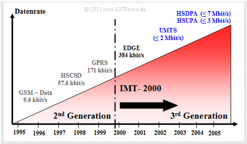
The main motivation for the development of 'Third generation mobile radio systems was the realization that 2G–systems could not satisfy the bandwidth requirements for the use of multimedia services.
The graph shows the development of mobile radio systems from 1995 to 2006 in terms of performance. The specified data rates were still realistic for 2011 with no more than two active users in one cell. The maximum values often stated by providers were mostly not reached in practice.
Third-generation mobile communications systems should have a greater bandwidth and sufficient reserve capacity to ensure a high quality of service (QoS) even with growing requirements.
Prior to the development of the 3G–systems, the International Telecommunication Union (ITU) created a catalog of requirements which includes the following general conditions:
- High data rates from $\text{144 kbit/s}$ (Standard) to $\text{2 Mbit/s}$ (In-door),
- symmetric and asymmetric data transmission (IP–services),
- high speech quality and high spectral efficiency,
- global accessibility and distribution,
- seamless transition from and to second generation systems,
- Applicability independent of the network used (Virtual Home Environment ),
- Provision of circuit-switched and packet-switched transmission.
During the introduction of UMTS (Universal Mobile Telecommunication System) as the best known 3G–standard, the expansion and diversification of the services offered was a decisive motive. A UMTS–capable terminal device must support a number of complex and multimedia applications in addition to the classic services (voice transmission, messaging, etc.), including >br>
- with regard to Information: Internet surfing (Info–on–demand), online print media,
- regarding Communication: video and audio conference, fax, ISDN, messaging,
- regarding Entertainment: Mobile TV, Video–on–Demand, Online–Gaming,
- in the business area: Interactive shopping, E–Commerce,
- in the technical area: Online–support, distribution service (language and data),
- in the medical field: telemedicine.
- Translated with www.DeepL.com/Translator (free version) ***
The IMT-2000 standard
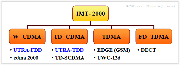
Around 1990, the International Telecommuncation Union (ITU) created the Standard IMT-2000 (International Mobile Telecommunications at the year 2000), which was to make the above-mentioned requirements possible. IMT–2000 comprises a number of third-generation mobile communications systems that have been brought closer together in the course of standardization to enable the development of common terminals for all these standards.
In order to take into account different preliminary work and to give network operators the possibility to continue to use existing network architectures in part, IMT–2000 contains several individual standards. These can be roughly divided into four categories:
- W–CDMA: This includes the FDD component of the European UMTS–standard and the American cdma2000–system.
- CDMA: This group includes the TDD–component of UMTS as well as the Chinese TD–SCDMA.
integrated in it.
- TDMA: A further development of the GSM–derived EDGE and its American counterpart UWC–136, also known as D–AMPS.
- FD–TDMA:nbsp; further development of the European cordless–telephony–DECT standard (Digital Enhanced Cordless Telecommunication).
We concentrate here on the mobile communications system UMTS developed in Europe, which supports the two standards W–CDMA and TD–CDMA of the system family IMT–2000, under the following designations:
- UTRA–FDD ⇒ UMTS Terrestrial Radio Access – Frequency Division Duplex:
This consists of twelve paired uplink and downlink frequency bands each $\text{5 MHz}$ bandwidth. In Europe these are between $\text{1920}$ and $\text{1980 MHz}$ in the uplink and between $\text{2110}$ and $\text{2170 MHz}$ in the downlink. In the summer of 2000, the auction of the licenses for Germany with a 20-year term brought in approx. 50 billion Euro.
- UTRA–TDD ⇒ UMTS Terrestrial Radio Access – Time Division Duplex:
Here, five bands of $\text{5 MHz}$ bandwidth are provided in which both uplink and downlink data are to be transmitted by means of time division multiplexing. For UTRA–TDD the frequencies between $\text{1900}$ and $\text{1920 MHz}$ (four channels) and between $\text{202020}$ and $\text{2025 MHz}$ (one channel) are reserved.
- Translated with www.DeepL.com/Translator (free version) ***
System architecture and basic units for UMTS
The network–architecture of UMTS can be divided into two main blocks.
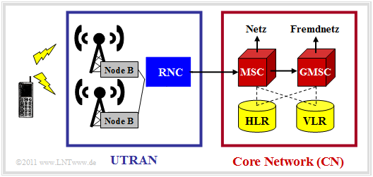
The UMTS Terrestrial Radio Access Network (UTRAN) ensures the wireless transmission of data between the transport level and the radio network level. This includes the base stations and the control nodes, whose functions are described below:
- A UMTS–base station is, also called Node B , comprises the antenna system and the CDMA–receiver and is directly connected to the radio interfaces of all users in the cell. The tasks of a "Node B" include data rate matching, data and channel (de)coding, interleaving, and modulation or demodulation. Each base station can serve one or more cells (sectors).
- The Radio Network Controller (RNC) is responsible for controlling the base stations. It is also responsible within the cells for call acceptance control, encryption and decryption, conversion to ATM (Asynchronous Tranfer Mode), channel assignment, handover and power control.
The Core Network (CN) takes over the switching of the data within the UMTS–network. For this purpose, it contains the following hardware and software components at circuit switching :
- The Mobile Switching Center (MSC) is responsible for localization/authentication, routing of calls, handover and encryption of user data.
- The Gateway Mobile Switching Center (GMSC) organizes the connection to other networks, for example to the landline network.
- MSC and GMSC have access to various databases like checkLink:_Buch_9 ⇒
Home Location Register (HLR) and checkLink:_Buch_9 ⇒ Visitor Location Register (VLR).
<The diagram shows the UMTS–architecture for circuit switching ( Circuit Switching ), where the Core Network (CN) is organized similar to the GSM–architecture.
The checkLink:_Buch_9 ⇒ System Architecture for Packet Switching (english: Packet Switching ) differs fundamentally from this:
- Here, the communication partners do not use the channel assigned to them exclusively, but the packets are mixed with those of other users.
- One finds there similar components as with the GSM–Extension checkLink:_Buch_9 ⇒ General Packet Radio Service (GPRS).
CDMA - Multiple access with UMTS
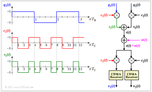
UMTS uses the multiple access method checkLink:_Buch_5 ⇒ Direct Sequence Code Division Multiple Access (DS–CDMA). The procedure is sometimes also called "PN–Modulation".
The diagram shows the principle using a simplified model and exemplary signals for the "user 1". For simplification the noise signal $n(t) \equiv 0$ is set for the displayed signals. It is valid:
- The two source signals $q_1(t)$ and $q_2(t)$ use the same AWGN–channel without interfering with each other. The bit duration of each data signal is $T_{\rm B}$.
.
- Each of the data signals is multiplied by an assigned spreading code, $c_1(t)$ or $c_2(t)$ . The sum signal is transmitted;
- $$s(t) = s_1(t) + s_2(t) = q_1(t) \cdot c_1(t) + q_2(t) \cdot c_2(t).$$
- The bandwidths of the partial signals $s_1(t)$ and $s_2(t)$ as well as of the resulting transmitedt signal $s(t)$ are larger than the bandwidths of $q_1(t)$ and $q_2(t)$ by the 'spreading factor $ J = T_{\rm C}/T_{\rm B}$ . For the graphic $J = 4$ was chosen.
- The same spreading codes $c_1(t)$ or $c_2(t)$ are added multiplicatively to the receiver. In the case of orthogonal codes and small AWGN–noise $n(t)$ the data signals can then be separated again. This means that $v_1(t) = q_1(t)$ and $v_2(t) = q_2(t)$.
- If AWGN–noise is present, the digital output signals are different from the input signals, but the probability of error is not increased by the other users as long as the used spreading sequences are orthogonal.
- In the example $J =4$ one could thus transmit users over the same channel without interference, but only if there are $J =4$ orthogonal spreading codes.
Requirements for the spreading codes
The spreading codes for UMTS should
- be orthogonal to each other to avoid mutual influence of the users,
- allow a flexible realization of different spreading factors $J$.
The situation described here is also clarified by the applet OVSF–Codes .
Zusätzliche Verwürfelung bei UMTS
Um mehr Spreizcodes zu erhalten und damit mehr Teilnehmer versorgen zu können, wird nach der Bandspreizung mit $c(t)$ die Folge mit $w(t)$ chipweise nochmals verwürfelt, ohne dass eine weitere Spreizung stattfindet.
Die Verwendung quasi–orthogonaler Codes macht Sinn, da die Menge an orthogonalen Codes begrenzt ist und durch die Verwürfelung verschiedene Teilnehmer auch gleiche Spreizcodes verwenden können.
$\text{Fazit:}$
- Der Verwürfelungscode $w(t)$ hat die gleiche Länge und dieselbe Rate wie $c(t)$.
- Durch die Verwürfelung (englisch: Scrambling ) verlieren die Codes ihre vollständige Orthogonalität; man nennt sie quasi–othogonal.
- Bei diesen Codes ist zwar die Kreuzkorrelationsfunktion (KKF) zwischen unterschiedlichen Spreizcodes ungleich Null.
- Sie zeichnen sich aber durch einen ausgeprägten AKF–Wert um den Nullpunkt aus, was die Detektion am Empfänger erleichtert.
$\text{Beispiel 2:}$ Bei UMTS verwendet man zur Verwürfelung so genannte Goldcodes:
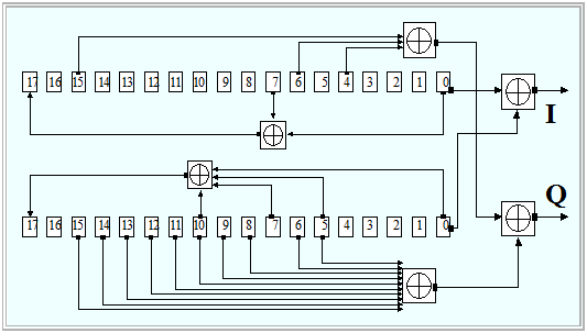
- Die Grafik aus [3gpp][1] zeigt das Blockschaltbild zur schaltungstechnischen Erzeugung solcher Codes.
- Dabei werden zunächst zwei unterschiedliche Pseudonoise–Folgen gleicher Länge $($hier: $N = 18)$ mit Hilfe von Schieberegistern parallel erzeugt und dann mit Exklusiv–Oder–Gatter bitweise addiert.
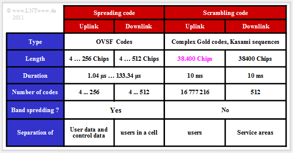
- Im Uplink hat jede Mobilstation einen eigenen Verwürfelungscode und die Trennung der einzelnen Kanäle erfolgt über den jeweils gleichen Code.
- Dagegen hat im Downlink jedes Versorgungsgebiet eines „Node B” einen gemeinsamen Verwürfelungscode.
- Die nebenstehende Tabelle fasst einige Daten der Spreiz– und Verwürfelungscodes zusammen.
Modulation und Pulsformung bei UMTS
Bei UMTS kommen im FDD–Modus folgende Modulationsverfahren zum Einsatz:
- Im Downlink findet Quaternary Phase Shift Keying (QPSK) Anwendung. Dabei werden Nutzdaten (DPDCH–Kanal) und Kontrolldaten (DPCCH–Kanal) zeitlich gemultiplext.
- Im Uplink wird eine zweifache binäre PSK (englisch: Dual–Channel–BPSK) verwendet. Diese besitzt zwar den gleichen Signalraum wie QPSK, aber die $I$– und $Q$–Komponenten übertragen hier die Informationen unterschiedlicher Kanäle.
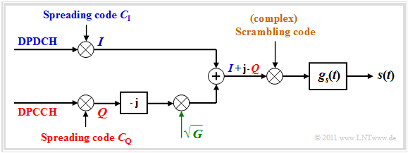
Die Grafik zeigt das $I/Q$–Multiplexing–Verfahren, wie Dual–Channel–BPSK auch genannt wird, im äquivalenten Tiefpassbereich.
- Die gespreizten Nutzdaten des DPDCH–Kanals werden auf die Inphase–Komponente $I$ (Realteil) und die Kontrolldaten des DPCCH–Kanals – ebenfalls mit einem Spreizcode beaufschlagt – auf die Quadratur–Komponente $Q$ (Imaginärteil) moduliert und übertragen.
- Die Quadratur–Komponente wird mit der Wurzel des Leistungsverhältnisses $G$ zwischen $I$ und $Q$ gewichtet, um Leistungsunterschiede auszugleichen. Anschließend wird das Summensignal $(I + {\rm j} \cdot Q)$ mit einem komplexen Verwürfelungscode multipliziert.
- Abschließend erfolgt die Impulsformung mit $g_s(t)$ entsprechend der Wurzel–Cosinus–Rolloff–Charakteristik (englisch: Root Raised Cosine). Da das Empfangsfilter an $G_s(f)$ angepasst ist, erfüllt somit der Gesamtfrequenzgang das erste Nyquistkriterium.
Weitere Informationen zu diesem Thema gibt es im Abschnitt Pulsformung und Modulation in UMTS des Buches „Beispiele von Nachrichtensystemen”. Dort finden Sie auch eine Grafik mit dem Nyquistfrequenzgang $H(f)$. Es handelt sich um einen Cosinus–Rolloff–Tiefpass (englisch: Raised Cosine) mit folgender Dimensionierung:
- Die UMTS–Chiprate beträgt $R_{\rm C} = 3.84 \ \rm Mbit/s$. Die Flankenmitte muss bei $f_{\rm N} =R_{\rm C}/2 = 1.92 \ \rm MHz$ liegen, um Impulsinterferenzen zu vermeiden. Dann gilt
- $$H(f = \pm f_{\rm N}) = 0.5.$$
- Für UMTS wurde der Rolloff–Faktor $r = 0.22$ festgelegt.
- Somit ergeben sich die beiden Eckfrequenzen zu $f_1 = 0.78 \cdot f_{\rm N} \approx 1.498 \ \rm MHz$ und $f_2 = 1.22 \cdot f_{\rm N} \approx 2.342 \ \rm MHz$.
- Die erforderliche absolute Frequenzbandbreite beträgt somit $B = 2 \cdot f_2 = 1.22 \cdot f_{\rm N} \approx 4.684 \ \rm MHz$, so dass für jeden UMTS–Kanal mit $5 \ \rm MHz$ ausreichend Bandbreite zur Verfügung steht.
UMTS–Erweiterungen HSDPA und HSUPA
Um dem ständig steigenden Bedarf an höheren Datenraten im Mobilfunk gerecht zu werden, wurde der UMTS–Standard stetig weiterentwickelt. Die wichtigsten Änderungen ergaben sich innerhalb der dritten Generation durch die Einführung von
- HSDPA: High Speed Downlink Packet Access (Release 5, 2002, Markteinführung 2006) und
- HSUPA: High Speed Uplink Packet Access (Release 6, 2005, Markteinführung 2007).
Zusammen ergeben HSDPA und HSDUPA den HSPA–Standard.
Hauptmotivation dieser Weiterentwicklungen war die Steigerung von Datenrate/ Durchsatz sowie die Minimierung der Antwortzeiten bei paketvermittelter Übertragung.
- Für die Abwärtsstrecke waren seit 2011 mit HSDPA Datenraten bis $\text{7 Mbit/s}$ durchaus machbar.
- Angegeben wurden aber auch (eher theoretische) Best–Case–Raten von bis zu $\text{28.8 Mbit/s}$ (bei 64–QAM und MIMO).
Erreicht wurden diese Steigerungen durch
- die Einführung zusätzlicher gemeinsam genutzter Kanäle (zum Beispiel HS–DSCH),
- das Hybrid–ARQ–Verfahren (HARQ) und Node B–Scheduling,
- die Verwendung von adaptiver $M$–QAM, Codierung und Übertragungsrate.
Die wesentliche Verbesserung durch HSUPA ist neben der Verwendung von HARQ und Node–B–Scheduling durch die Einführung des zusätzlichen Aufwärtskanals E–DCH (Enhanced Dedicated Channel) zurückzuführen.
- Dieser minimiert unter anderem den Einfluss von Anwendungen mit stark unterschiedlichen und teilweise sehr intensivem Datenaufkommen (englisch: Bursty Traffic ). Allerdings wird bei HSUPA im Gegensatz zu UMTS–R99 in Aufwärtsrichtung keine feste Bandbreite garantiert.
- Diese flexible und effiziente Bandbreitenzuteilung abhängig von den Kanalbedingungen steigerte die Zellenkapazität enorm. In der Praxis wurden ab 2011 auch bei Berücksichtigung vieler Nutzer Übertragungsraten bis zu $\text{3 Mbit/s}$ erreicht. Die von Entwicklern für beste Bedingungen angegebenen Werte lagen deutlich darüber.
Aufgaben zum Kapitel
Exercise 3.6: FDMA, TDMA and CDMA
Aufgabe 3.6Z: Begriffe der 3G–Mobilfunksysteme
Aufgabe 3.7Z: Zur Bandspreizung bei UMTS
Aufgabe 3.9: GSM/UMTS–Weiterentwicklungen
Quellenverzeichnis
- ↑ 3gpp Group: UMTS Release 6 – Technical Specification 25.213 V6.4.0., Sept. 2005.
