Difference between revisions of "Information Theory/Further Source Coding Methods"
| Line 134: | Line 134: | ||
| − | == | + | ==Run–Length Coding == |
<br> | <br> | ||
| − | + | We consider a binary source $(M = 2)$ with the symbol set $\{$ $\rm A$, $\rm B$ $\}$, where one symbol occurs much more frequently than the other. For example, let $p_{\rm A} \gg p_{\rm B}$. | |
| − | * | + | *Entropy coding only makes sense here when applied to $k$–tuples. |
| − | * | + | *A second possibility is '''Run-length coding''' (RLC), which considers the rarer character $\rm B$ as a separator and returns the lengths $L_i$ der einzelnen Substrings $\rm AA\text{...}A$ as a result. |
{{GraueBox|TEXT= | {{GraueBox|TEXT= | ||
| − | $\text{ | + | $\text{Example 5:}$ The graphic shows an example sequence with the probabilities $p_{\rm A} = 0.9$ and $p_{\rm B} = 0.1$ ⇒ source entropy $H = 0.469$ bit/source symbol. |
| − | + | The example sequence of length $N = 100$ contains symbol $\rm B$ exactly ten times and symbol $\rm A$ ninety times, i.e. the relative frequencies here correspond exactly to the probabilities. | |
| − | |||
| − | + | [[File:P_ID2470__Inf_T_2_4_S4_neu.png|center|frame|To illustrate the run length coding]] | |
| − | * | + | |
| + | You can see from this example: | ||
| + | *The run length coding of this sequence results in the sequence $ \langle \hspace{0.05cm}6, \ 14, \ 26, \ 11, \ 4, \ 10, \ 3,\ 9,\ 1,\ 16 \hspace{0.05cm} \rangle $. | ||
*Stellt man die Längen $L_1$, ... , $L_{10}$ mit jeweils fünf Bit dar, so benötigt man so $5 · 10 = 50$ Bit. | *Stellt man die Längen $L_1$, ... , $L_{10}$ mit jeweils fünf Bit dar, so benötigt man so $5 · 10 = 50$ Bit. | ||
*Die RLC–Datenkomprimierung ist also nicht viel schlechter als der theoretische Grenzwert, der sich entsprechend der Quellenentropie zu $H · N ≈ 47$ Bit ergibt. | *Die RLC–Datenkomprimierung ist also nicht viel schlechter als der theoretische Grenzwert, der sich entsprechend der Quellenentropie zu $H · N ≈ 47$ Bit ergibt. | ||
Revision as of 14:43, 29 March 2021
Contents
The Shannon-Fano algorithm
The Huffman coding from 1952 is a special case of „entropy coding”. It attempts to represent the source symbol $q_μ$ by a code symbol $c_μ$ of length $L_μ$ , aiming for the following construction rule:
- $$L_{\mu} \approx -{\rm log}_2\hspace{0.15cm}(p_{\mu}) \hspace{0.05cm}.$$
Since $L_μ$ , in contrast to $-{\rm log}_2\hspace{0.15cm}(p_{\mu})$ , is integer, this does not always succeed.
Already three years before David A. Huffman, Claude E. Shannon and Robert Fano gave a similar algorithm, namely:
- Order the source symbols according to decreasing probabilities of occurrence (identical to Huffman).
- Divide the sorted characters into two groups of equal probability.
- The binary symbol 1 is assigned to the first group, 0 to the second (or vice versa).
- If there is more than one character in a group, the algorithm is to be applied recursively to this group.
$\text{Example 1:}$ As in the introductory example for the Huffman algorithm in the last chapter, we assume $M = 6$ symbols and the following probabilities:
- $$p_{\rm A} = 0.30 \hspace{0.05cm},\hspace{0.2cm}p_{\rm B} = 0.24 \hspace{0.05cm},\hspace{0.2cm}p_{\rm C} = 0.20 \hspace{0.05cm},\hspace{0.2cm} p_{\rm D} = 0.12 \hspace{0.05cm},\hspace{0.2cm}p_{\rm E} = 0.10 \hspace{0.05cm},\hspace{0.2cm}p_{\rm F} = 0.04 \hspace{0.05cm}.$$
Then the Shannon-Fano algorithm is:
- $\rm AB$ → 1x (probability 0.54), $\rm CDEF$ → 0x (probability 0.46),
- $\underline{\rm A}$ → 11 (probability 0.30), $\underline{\rm B}$ → 10 (probability 0.24),
- $\underline{\rm C}$ → 01 (probability 0.20), $\rm DEF$ → 00x, (probability 0.26),
- $\underline{\rm D}$ → 001 (probability 0.12), $\rm EF$ → 000x (probability 0.14),
- $\underline{\rm E}$ → 0001 (probability 0.10), $\underline{\rm F}$ → 0000 (probability 0.04).
Notes:
- An „x” again indicates that bits must still be added in subsequent coding steps.
- This results in a different assignment than with Huffman coding, but exactly the same average codeword length: Huffman coding, but exactly the same average codeword length:
- $$L_{\rm M} = (0.30\hspace{-0.05cm}+\hspace{-0.05cm} 0.24\hspace{-0.05cm}+ \hspace{-0.05cm}0.20) \hspace{-0.05cm}\cdot\hspace{-0.05cm} 2 + 0.12\hspace{-0.05cm} \cdot \hspace{-0.05cm} 3 + (0.10\hspace{-0.05cm}+\hspace{-0.05cm}0.04) \hspace{-0.05cm}\cdot \hspace{-0.05cm}4 = 2.4\,{\rm bit/source symbol}\hspace{0.05cm}.$$
With the probabilities corresponding to $\text{example 1}$ , the Shannon-Fano algorithm leads to the same mean codeword length as Huffman coding. Similarly, for many (actually: most) other probability profiles, Huffman and Shannon-Fano are equivalent from an information-theoretic point of view.
However, there are definitely cases where the two methods differ in terms of (mean) codeword length, as the following example shows.
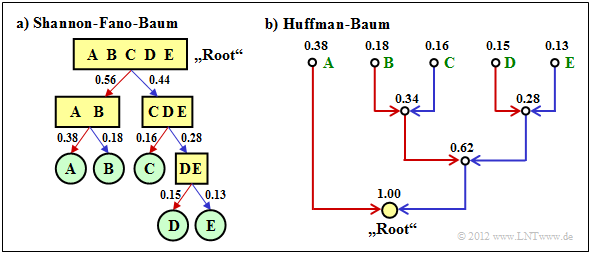
$\text{Example 2:}$ We consider $M = 5$ symbols with the following probabilities:
- $$p_{\rm A} = 0.38 \hspace{0.05cm}, \hspace{0.2cm}p_{\rm B}= 0.18 \hspace{0.05cm}, \hspace{0.2cm}p_{\rm C}= 0.16 \hspace{0.05cm},\hspace{0.2cm} p_{\rm D}= 0.15 \hspace{0.05cm}, \hspace{0.2cm}p_{\rm E}= 0.13 \hspace{0.3cm} \Rightarrow\hspace{0.3cm} H = 2.19\,{\rm bit/source symbol} \hspace{0.05cm}. $$
The diagram shows the respective code trees for Shannon-Fano (left) and Huffman (right). The results can be summarised as follows:
- The Shannon-Fano algorithm leads to the code $\rm A$ → 11, $\rm B$ → 10, $\rm C$ → 01, $\rm D$ → 001, $\rm E$ → 000 and thus to the mean code word length
- $$L_{\rm M} = (0.38 + 0.18 + 0.16) \cdot 2 + (0.15 + 0.13) \cdot 3 = 2.28\,\,{\rm bit/source symbol}\hspace{0.05cm}.$$
- Using „Huffman”, we get $\rm A$ → 1, $\rm B$ → 001, $\rm C$ → 010, $\rm D$ → 001, $\rm E$ → 000 and a slightly smaller mean codeword length:
- $$L_{\rm M} = 0.38 \cdot 1 + (1-0.38) \cdot 3 = 2.24\,\,{\rm bit/source symbol}\hspace{0.05cm}. $$
- There is no set of probabilities for which „Shannon–Fano” provides a better result than the Huffman algorithm, which always provides the best possible entropy encoder.
- The graph also shows that the algorithms proceed in different directions in the tree diagram, namely once from the root to the individual symbols (Shannon–Fano, and secondly from the individual symbols to the root (Huffman).
Arithmetic coding
Another form of entropy coding is arithmetic coding. Here, too, the symbol probabilities $p_μ$ must be known. For the index, $μ = 1$, ... , $M$.
Here is a brief outline of the procedure:
- In contrast to Huffman and Shannon-Fano coding, a symbol sequence of length $N$ is coded together in arithmetic coding. We write abbreviated $Q = 〈\hspace{0.05cm} q_1, q_2$, ... , $q_N \hspace{0.05cm} 〉$.
- Each symbol sequence $Q_i$ is assigned a real number interval $I_i$ which is identified by the beginning $B_i$ and the interval width ${\it Δ}_i$ .
- The „code” for the sequence $Q_i$ is the binary representation of a real number value from this interval: $r_i ∈ I_i = \big [B_i, B_i + {\it Δ}_i\big)$. This notation says that $B_i$ belongs to the interval $I_i$ (square bracket), but $B_i + {\it Δ}_i$ just does not (round bracket).
- It is always $0 ≤ r_i < 1$. It makes sense to select $r_i$ from the interval $I_i$ in such a way that the value can be represented with as few bits as possible. However, there is always a minimum number of bits, which depends on the interval width ${\it Δ}_i$ .
The algorithm for determining the interval parameters $B_i$ and ${\it Δ}_i$ is explained later in $\text{example 4}$ , as is a decoding option.
- First, there is a short example for the selection of the real number $r_i$ with regard to the minimum number of bits.
- More detailed information on this can be found in the description of task 2.11Z.
$\text{Example 3:}$ For the two parameter sets of the arithmetic coding algorithm listed below, the following real results $r_i$ and the following codes belong to the associated interval $I_i$ :
- $B_i = 0.25, {\it Δ}_i = 0.10 \ ⇒ \ I_i = \big[0.25, 0.35\big)\text{:}$
- $$r_i = 0 \cdot 2^{-1} + 1 \cdot 2^{-2} = 0.25 \hspace{0.3cm}\Rightarrow\hspace{0.3cm} {\rm Code} \hspace{0.15cm} \boldsymbol{\rm 01} \in I_i \hspace{0.05cm},$$
- $B_i = 0.65, {\it Δ}_i = 0.10 \ ⇒ \ I_i = \big[0.65, 0.75\big);$ note: $0.75$ does not belong to the interval:
- $$r_i = 1 \cdot 2^{-1} + 0 \cdot 2^{-2} + 1 \cdot 2^{-3} + 1 \cdot 2^{-4} = 0.6875 \hspace{0.3cm}\Rightarrow\hspace{0.3cm} {\rm Code} \hspace{0.15cm} \boldsymbol{\rm 1011} \in I_i\hspace{0.05cm}. $$
However, to organise the sequential flow, one chooses the number of bits constant to $N_{\rm Bit} = \big\lceil {\rm log}_2 \hspace{0.15cm} ({1}/{\it \Delta_i})\big\rceil+1\hspace{0.05cm}. $
- With the interval width ${\it Δ}_i = 0.10$ results $N_{\rm Bit} = 5$.
- So the actual arithmetic codes would be 01000 and 10110 respectively.
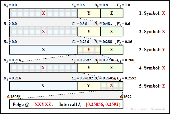
$\text{Example 4:}$ Now let the symbol range be $M = 3$ and let the symbols be denoted by $\rm X$, $\rm Y$ and $\rm Z$:
- The character sequence $\rm XXYXZ$ ⇒ length of the source symbol sequence: $N = 5$.
- Assume the probabilities $p_{\rm X} = 0.6$, $p_{\rm Y} = 0.2$ und $p_{\rm Z} = 0.2$.
The diagram shows the algorithm for determining the interval boundaries.
- First, the entire probability range $($between $0$ and $1)$ is divided according to the symbol probabilities $p_{\rm X}$, $p_{\rm Y}$ and $p_{\rm Z}$ into three areas with the boundaries $B_0$, $C_0$, $D_0$ and $E_0$.
- The first symbol present for coding is $\rm X$. Therefore, in the next step, the probability range from $B_1 = B_0 = 0$ to $E_1 = C_0 = 0.6$ is again divided in the ratio $0.6$ : $0.2$ : $0.2$ .
- After the second symbol $\rm X$ , the range limits are $B_2 = 0$, $C_2 = 0.216$, $D_2 = 0.288$ and $E_2 = 0.36$. Since the symbol $\rm Y$ is now pending, the range is subdivided between $0.216$ ... $0.288$.
- After the fifth symbol $\rm Z$ , the interval $I_i$ for the considered symbol sequence $Q_i = \rm XXYXZ$ is fixed. A real number $r_i$ must now be found for which the following applies:: $0.25056 ≤ r_i < 0.2592$.
- The only real number in the interval $I_i = \big[0.25056, 0.2592\big)$, that can be represented with seven bits is $r_i = 1 · 2^{–2} + 1 · 2^{–7} = 0.2578125$. Thus the coder output is fixed: 0100001.
Seven bits are therefore needed for these $N = 5$ symbols, exactly as many as with Huffman coding with the assignment $\rm X$ → 1, $\rm Y$ → 00, $\rm Z$ → 01.
- However, arithmetic coding is superior to Huffman coding when the actual number of bits used in Huffman deviates even more from the optimal distribution, for example, when a character occurs extremely frequently.
- Often, however, only the middle of the interval – in the example $0.25488$ – is represented in binary: 0.01000010011 .... The number of bits is obtained as follows:
- $${\it Δ}_5 = 0.2592 - 0.25056 = 0.00864 \hspace{0.3cm}\Rightarrow \hspace{0.3cm}N_{\rm Bit} = \left\lceil {\rm log}_2 \hspace{0.15cm} \frac{1}{0.00864} \right\rceil + 1\hspace{0.15cm} = \left\lceil {\rm log}_2 \hspace{0.15cm} 115.7 \right\rceil + 1 = 8 \hspace{0.05cm}.$$
- Thus the arithmetic code for this example with $N = 5$ input characters is: 01000010.
- The decoding process can also be explained using the above graphic. The incoming bit sequence 0100001 wird zu $r = 0.2578125$ is converted to.
- This lies in the first and second step respectively in the first area ⇒ symbol $\rm X$, in the third step in the second area ⇒ symbol $\rm Y$, etc.
Further information on arithmetic coding can be found in WIKIPEDIA and in [BCK02][1].
Run–Length Coding
We consider a binary source $(M = 2)$ with the symbol set $\{$ $\rm A$, $\rm B$ $\}$, where one symbol occurs much more frequently than the other. For example, let $p_{\rm A} \gg p_{\rm B}$.
- Entropy coding only makes sense here when applied to $k$–tuples.
- A second possibility is Run-length coding (RLC), which considers the rarer character $\rm B$ as a separator and returns the lengths $L_i$ der einzelnen Substrings $\rm AA\text{...}A$ as a result.
$\text{Example 5:}$ The graphic shows an example sequence with the probabilities $p_{\rm A} = 0.9$ and $p_{\rm B} = 0.1$ ⇒ source entropy $H = 0.469$ bit/source symbol.
The example sequence of length $N = 100$ contains symbol $\rm B$ exactly ten times and symbol $\rm A$ ninety times, i.e. the relative frequencies here correspond exactly to the probabilities.
You can see from this example:
- The run length coding of this sequence results in the sequence $ \langle \hspace{0.05cm}6, \ 14, \ 26, \ 11, \ 4, \ 10, \ 3,\ 9,\ 1,\ 16 \hspace{0.05cm} \rangle $.
- Stellt man die Längen $L_1$, ... , $L_{10}$ mit jeweils fünf Bit dar, so benötigt man so $5 · 10 = 50$ Bit.
- Die RLC–Datenkomprimierung ist also nicht viel schlechter als der theoretische Grenzwert, der sich entsprechend der Quellenentropie zu $H · N ≈ 47$ Bit ergibt.
- Die direkte Anwendung einer Entropiecodierung hätte hier keine Datenkomprimierung zur Folge; man benötigt weiterhin vielmehr weiterhin $100$ Bit.
- Auch bei der Bildung von Dreiertupeln würde man mit Huffman noch $54$ Bit benötigen, also mehr als mit Run–Length Coding.
Das Beispiel zeigt aber auch zwei Probleme der Lauflängencodierung auf:
- Die Längen $L_i$ der Substrings sind nicht begrenzt. Hier muss man besondere Maßnahmen treffen, wenn eine Länge $L_i$ größer ist als $2^5 = 32$ $($gültig für $N_{\rm Bit} = 5)$, zum Beispiel die Variante Run–Length Limited Coding (RLLC). Siehe auch [Meck09][2] und Aufgabe 2.13.
- Endet die Folge nicht mit $\rm B$ – was bei kleiner Wahrscheinlichkeit $p_{\rm B}$ eher der Normalfall ist, so muss man auch für das Dateiende eine Sonderbehandlung vorsehen.
Burrows–Wheeler–Transformation
Zum Abschluss dieses Quellencodier–Kapitels behandeln wir noch kurz den 1994 von Michael Burrows und David J. Wheeler veröffentlichten Algorithmus [BW94][3],
- der zwar alleine keinerlei Komprimierungspotenzial besitzt,
- aber die Komprimierungsfähigkeit anderer Verfahren stark verbessert.
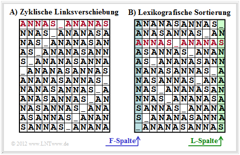
Die Burrows–Wheeler–Transformation bewerkstelligt eine blockweise Sortierung von Daten, die in der Grafik am Beispiel des Textes $\text{ANNAS_ANANAS}$ der Länge $N = 12$ verdeutlicht wird:
- Zunächst wird aus dem String der Länge $N$ eine $N×N$–Matrix erzeugt, wobei sich jede Zeile aus der Vorgängerzeile durch zyklische Linksverschiebung ergibt.
- Danach wird die BWT–Matrix lexikografisch sortiert. Das Ergebnis der Transformation ist die letzte Spalte ⇒ $\text{L–Spalte}$. Im Beispiel ergibt sich $\text{_NSNNAANAAAS}$.
- Des Weiteren muss auch der Primärindex $I$ weitergegeben werden. Dieser gibt die Zeile der sortierten BWT–Matrix an, die den Originaltext enthält (in der Grafik rot markiert).
- Zur Bestimmung von L–Spalte und Primärindex sind natürlich keine Matrixoperationen erforderlich. Vielmehr findet man das BWT–Ergebnis mit Zeigertechnik sehr schnell.
$\text{Außerdem ist zum BWT–Verfahren anzumerken:}$
- Ohne Zusatzmaßnahme ⇒ eine nachgeschaltete „echte Kompression” – führt die BWT zu keiner Datenkomprimierung.
- Vielmehr ergibt sich sogar eine geringfügige Erhöhung der Datenmenge, da außer den $N$ Zeichen nun auch der Primärindex $I$ übermittelt werden muss.
- Bei längeren Texten ist dieser Effekt aber vernachlässigbar. Geht man von 8 Bit–ASCII–Zeichen (jeweils ein Byte) und der Blocklänge $N = 256$ aus, so erhöht sich die Byte–Anzahl pro Block nur von $256$ auf $257$, also lediglich um $0.4\%$.
Wir verweisen auf die ausführlichen Beschreibungen zur BWT in [Abel04][4].
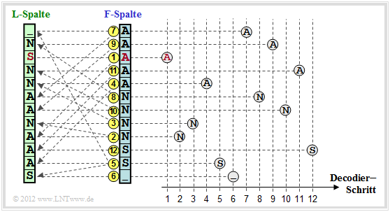
Abschließend soll noch dargestellt werden, wie der Ursprungstext aus der $\text{L–Spalte}$ der BWT–Matrix rekonstruiert werden kann.
- Dazu benötigt man noch den Primärindex $I$, sowie die erste Spalte der BWT–Matrix.
- Diese $\text{F–Spalte}$ (von „First”) muss nicht übertragen werden, sondern ergibt sich aus der $\text{L–Spalte}$ (von „Last”) sehr einfach durch lexikografische Sortierung.
Die Grafik zeigt die Vorgehensweise für das betrachtete Beispiel:
- Man beginnt in der Zeile mit dem Primärindex $I$. Als erstes Zeichen wird das rot markierte $\rm A$ in der $\text{F–Spalte}$ ausgegeben. Dieser Schritt ist in der Grafik mit einer gelben (1) gekennzeichnet.
- Dieses $\rm A$ ist das dritte $\rm A$–Zeichen in der $\text{F–Spalte}$. Man sucht nun das dritte $\rm A$ in der $\text{L–Spalte}$, findet dieses in der mit (2) markierten Zeile und gibt das zugehörige N der $\text{F–Spalte}$ aus.
- Das letzte N der $\text{L–Spalte}$ findet man in der Zeile (3). Ausgegeben wird das Zeichen der F–Spalte in der gleichen Zeile, also wieder ein N.
Nach $N = 12$ Decodierschritten ist die Rekonstruktion abgeschlossen.
$\text{Fazit:}$
- Dieses Beispiel hat gezeigt, dass die Burrows–Wheeler–Transformation nichts anderes ist als ein Sortieralgorithmus für Texte. Das Besondere daran ist, dass die Sortierung eindeutig umkehrbar ist.
- Diese Eigenschaft und zusätzlich seine innere Struktur sind die Grundlage dafür, dass man das BWT–Ergebnis mittels bekannter und effizienter Verfahren wie Huffman (eine Form der Entropiecodierung) und Run–Length Coding komprimieren kann.
Anwendungsszenario für die Burrows–Wheeler–Transformation
Als Beispiel für die Einbettung der Burrows–Wheeler–Transformation (BWT) in eine Kette von Quellencodierverfahren wählen wir eine in [Abel03][5] vorgeschlagene Struktur. Wir verwenden dabei das gleiche Textbeispiel $\text{ANNAS_ANANAS}$ wie auf der letzten Seite. Die entsprechenden Strings nach den einzelnen Blöcken sind in der Grafik ebenfalls angegeben.
- Das BWT–Ergebnis lautet: $\text{_NSNNAANAAAS}$. An der Textlänge $N = 12$ hat die BWT nichts verändert, doch gibt es jetzt vier Zeichen, die identisch mit ihren Vorgängerzeichen sind (in der Grafik rot hervorgehoben). Im Originaltext war dies nur einmal der Fall.
- Im nächsten Block MTF (Move–To–Front) wird aus jedem Eingangszeichen aus der Menge $\{$ $\rm A$, $\rm N$, $\rm S$, _$\}$ ein Index $I ∈ \{0, 1, 2, 3\}$. Es handelt sich hierbei aber nicht um ein einfaches Mapping, sondern um einen Algorithmus, der in der Aufgabe 1.13Z angegeben ist.
- Für unser Beispiel lautet die MTF–Ausgangsfolge $323303011002$, ebenfalls mit der Länge $N = 12$. Die vier Nullen in der MTF–Folge (in der Grafik ebenfalls mit roter Schrift) geben an, dass an diesen Stellen das BWT–Zeichen jeweils gleich ist wie sein Vorgänger.
- Bei großen ASCII–Dateien kann die Häufigkeit der $0$ durchaus mehr als $50\%$ betragen, während die anderen $255$ Indizes nur selten auftreten. Zur Komprimierung einer solchen Textstruktur eignet sich eine Lauflängencodierung (englisch: Run–Length Coding, RLC) hervorragend.
- Der Block RLC0 in obiger Codierungskette bezeichnet eine spezielle Lauflängencodierung für Nullen. Die graue Schattierung der Nullen soll andeuten, dass hier eine lange Nullsequenz durch eine spezifische Bitfolge (kürzer als die Nullsequenz) maskiert wurde.
- Der Entropiecodierer $($EC, zum Beispiel „Huffman”$)$ sorgt für eine weitere Komprimierung. BWT und MTF haben in der Codierungskette nur die Aufgabe, durch eine Zeichenvorverarbeitung die Effizienz von RLC0 und EC zu steigern. Die Ausgangsdatei ist wieder binär.
Aufgaben zum Kapitel
Aufgabe 2.10: Shannon-Fano-Codierung
Aufgabe 2.11: Arithmetische Codierung
Aufgabe 2.11Z: Nochmals Arithmetische Codierung
Aufgabe 2.12: Run–Length Coding & RLLC
Aufgabe 2.13: Burrows-Wheeler-Rücktransformation
Aufgabe 2.13Z: Kombination BWT & „Move-to-Front”
Quellenverzeichnis
- ↑ Bodden, E.; Clasen, M.; Kneis, J.: Algebraische Kodierung. Proseminar, Lehrstuhl für Informatik IV, RWTH Aachen, 2002.
- ↑ Mecking, M.: Information Theory. Vorlesungsmanuskript, Lehrstuhl für Nachrichtentechnik, Technische Universität München, 2009.
- ↑ Burrows, M.; Wheeler, D.J.: A Block-sorting Lossless Data Compression Algorithm. Technical Report. Digital Equipment Corporation Communications, Palo Alto, 1994.
- ↑ Abel, J.: Grundlagen des Burrows-Wheeler-Kompressionsalgorithmus. In: Informatik Forschung & Entwicklung, no. 2, vol. 18, S. 80-87, Jan. 2004
- ↑ Abel, J.: Verlustlose Datenkompression auf Grundlage der Burrows-Wheeler-Transformation. In: PIK - Praxis der Informationsverarbeitung und Kommunikation, no. 3, vol. 26, S. 140-144, Sept. 2003.


