Difference between revisions of "Aufgaben:Exercise 1.3Z: Thermal Noise"
m |
|||
| Line 37: | Line 37: | ||
Hints: | Hints: | ||
*This exercise belongs to the chapter [[Modulation_Methods/Qualitätskriterien|Quality Criteria]]. | *This exercise belongs to the chapter [[Modulation_Methods/Qualitätskriterien|Quality Criteria]]. | ||
| − | * | + | *Particular reference is made to the page [[Modulation_Methods/Quality_Criteria#Some_remarks_on_the_AWGN_channel_model|Some remarks on the AWGN channel model]]. |
| − | |||
*By specifying the powers in $\rm W$atts , they are independent of the reference resistance $R$, while power with the unit $\rm V^2$ can only be evaluated directly for $R = 1\ \Omega$. | *By specifying the powers in $\rm W$atts , they are independent of the reference resistance $R$, while power with the unit $\rm V^2$ can only be evaluated directly for $R = 1\ \Omega$. | ||
Revision as of 10:56, 24 November 2021
A fundamental disturbance and one that occurs in any communication system is "thermal noise", since any resistance $R$ with an absolute temperature of $θ$ (in "degrees Kelvin") produces a noise signal $n(t)$ with a (one-sided) noise power density
- $${N_{\rm 0, \hspace{0.05cm}min}}= k_{\rm B} \cdot \theta \hspace{0.3cm}\left(k_{\rm B} = 1.38 \cdot 10^{-23} \hspace{0.05cm}{\rm Ws}/{\rm K}\right)$$
where $k_{\rm B}$ denotes the "Boltzmann constant" (from German "Konstante").
However, this noise is limited to $6\text{ THz}$ for physical reasons. Furthermore, it can be observed that this minimum value can only be achieved with exact impedance matching.
In the realization of a circuit unit - for example, an amplifier - the effective noise power density is usually significantly greater, since several noise sources add up, and mismatches also play a role. This effect is captured by the noise factor $F \ge 1$ . It holds that:
- $$N_0 = F \cdot {N_{\rm 0, \hspace{0.05cm}min}}= F \cdot k_{\rm B} \cdot \theta \hspace{0.05cm}.$$
With a bandwidth $B$, the effective noise power is characterized by:
- $$N = N_0 \cdot B \hspace{0.1cm} \hspace{0.01cm}.$$
- $$N = N_0 \cdot B\cdot R = \sigma_n^2 \hspace{0.01cm}.$$
- According to the first equation, the result is the actual, physical power in "watts" $\rm (W)$.
- According to the second equation, the result has the unit „$\rm V^{ 2 }$”.
- This means that the power is here converted to the reference resistance $R = 1\ Ω$ – as is often the case in Communications Engineering.
- This equation must also be used to calculate the rms value ("standard deviation") $σ_n$ of the noise signal $n(t)$ .
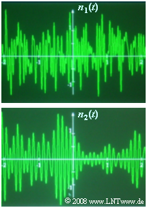
All equations apply regardless of whether the noise is low-pass or band-pass. The diagram shows two noise signals $n_1(t)$ and $n_2(t)$ of equal bandwidth. Question (4) asks which of these signals will appear at the output of a low-pass and a band-pass, respectively.
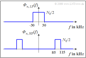
The two-sided noise power density of band-limited low-pass noise $n_{\rm TP}(t)$ is:
- $$ {\it \Phi}_{n, {\hspace{0.05cm}\rm LP}}(f) = \left\{ \begin{array}{c} N_0/2 \\ 0 \\ \end{array} \right. \begin{array}{*{10}c} {\rm{for}} \\ \\ \end{array}\begin{array}{*{20}c} {\left| \hspace{0.005cm} f\hspace{0.05cm} \right| < B,} \\ {\rm otherwise.} \\ \end{array}$$
In contrast, for band-pass noise $n_{\rm BP}(t)$ with center frequency $f_{\rm M}$, it holds that:
- $${\it \Phi}_{n, {\hspace{0.05cm}\rm BP}}(f) = \left\{ \begin{array}{c} N_0/2 \\ 0 \\ \end{array} \right. \begin{array}{*{10}c} {\rm{for}} \\ \\ \end{array}\begin{array}{*{20}c} {\left| \hspace{0.005cm} f - f_{\rm M}\hspace{0.05cm} \right| < B/2,} \\ {\rm otherwise.} \\ \end{array}.$$
For all subsequent numerical calculations it is assumed:
- $$ F = 10, \hspace{0.2cm}\theta = 290\,{\rm K},\hspace{0.2cm}R = 50\,{\rm \Omega},\hspace{0.2cm}B = 30\,{\rm kHz},\hspace{0.2cm}f_{\rm M} = 0 \hspace{0.5cm}{\rm or}\hspace{0.5cm}f_{\rm M} =100\,{\rm kHz}\hspace{0.05cm}.$$
Hints:
- This exercise belongs to the chapter Quality Criteria.
- Particular reference is made to the page Some remarks on the AWGN channel model.
- By specifying the powers in $\rm W$atts , they are independent of the reference resistance $R$, while power with the unit $\rm V^2$ can only be evaluated directly for $R = 1\ \Omega$.
Questions
Solution
- $$N_0 = F \cdot k_{\rm B} \cdot \theta = 10 \cdot 1.38\hspace{0.05cm}\cdot 10^{-23} \hspace{0.05cm}\frac{\rm Ws}{\rm K}\cdot 290\,{\rm K} \hspace{0.15cm}\underline {\approx 4\hspace{0.05cm}\cdot 10^{-20} \hspace{0.05cm}{\rm W}/{\rm Hz}}\hspace{0.05cm}.$$
(2) The specified noise power density $N_0$ is physically limited to $6$ THz. Thus the maximum noise power is:
- $$N_{\rm max} = 4\hspace{0.05cm}\cdot 10^{-20} \hspace{0.08cm}\frac{\rm W}{\rm Hz}\cdot 6 \cdot10^{12} \hspace{0.08cm}{\rm Hz}\hspace{0.15cm}\underline {= 0.24\hspace{0.08cm}\cdot 10^{-6}\;{\rm W}}\hspace{0.05cm}.$$
(3) Now the resulting noise power is:
- $$N = N_0 \cdot B = 4\hspace{0.08cm}\cdot 10^{-20} \hspace{0.08cm}\frac{\rm W}{\rm Hz}\cdot 3 \cdot10^{4} \hspace{0.08cm}{\rm Hz}\hspace{0.15cm}\underline {= 12\hspace{0.05cm}\cdot 10^{-16}\;{\rm W}}\hspace{0.05cm}.$$
- Converting to the reference resistance $R = 1 \ Ω$:
- $$N = N_0 \cdot B \cdot R = 12\hspace{0.05cm}\cdot 10^{-16}\;{\rm W}\hspace{0.05cm} \cdot 50 \; {\rm \Omega}= 6\hspace{0.05cm}\cdot 10^{-14}\;{\rm V^2}\hspace{0.05cm}.$$
- The noise rms value $σ_n$ is the square root of this:
- $$\sigma_n= \sqrt{6\hspace{0.05cm}\cdot 10^{-14}\;{\rm V^2}} \hspace{0.15cm}\underline {= 0.245 \hspace{0.05cm}\cdot 10^{-6}\;{\rm V}}\hspace{0.05cm}.$$
(4) Answer 1 is correct:
- In the random signal $n_2(t)$ one can recognize certain regularities similar to a harmonic oscillation ⇒ it is bandpass noise.
- In contrast, the signal $n_1(t)$ is low-pass noise.
(5) The noise power density of the random signal $n_1(t)$ is constant in the frequency range $|f| < 30$ kHz:
- $${\it \Phi}_{n,\hspace{0.05cm}{ \rm LP} }(f) \hspace{-0.05cm}=\hspace{-0.05cm} \frac{N_0}{2} \hspace{0.15cm}\underline {=2\hspace{0.05cm}\hspace{-0.05cm}\cdot \hspace{-0.05cm} 10^{-12} \hspace{0.05cm}{\rm W}/{\rm Hz}}\hspace{0.05cm}.$$
- Thus, this value is also valid for the frequency $f = 20$ kHz.
(6) As can be seen from the diagram, ${\it Φ}_{n, \hspace{0.05cm}\rm BP}(f)$ is non-zero only in the range between $85$ kHz and $115$ kHz, when the bandwidth is $B = 30$ kHz.
- Thus, at the frequency $f = 120$ kHz, the noise power density is zero:
- $${\it Φ}_{n, \hspace{0.05cm}\rm BP}(f = 120 \ \rm kHz)\hspace{0.15cm}\underline{=0}.$$

