Difference between revisions of "Aufgaben:Exercise 2.4Z: Low-pass Influence with Synchronous Demodulation"
m |
m |
||
| Line 33: | Line 33: | ||
''Hints:'' | ''Hints:'' | ||
*This exercise belongs to the chapter [[Modulation_Methods/Synchronous_Demodulation|Synchronous Demodulation]]. | *This exercise belongs to the chapter [[Modulation_Methods/Synchronous_Demodulation|Synchronous Demodulation]]. | ||
| − | *Particular reference is made to the page [[Modulation_Methods/Synchronous_Demodulation#Block_diagram_and_time_domain_representation| | + | *Particular reference is made to the page [[Modulation_Methods/Synchronous_Demodulation#Block_diagram_and_time_domain_representation|Block diagram and time domain representation]]. |
*In contrast to [[Aufgaben:Exercise_2.4:_Frequency_and_Phase_Offset|Exercise 2.4]] , $f_1$ and $f_2$ do not describe signal frequencies, but instead relate to the low-pass filter. | *In contrast to [[Aufgaben:Exercise_2.4:_Frequency_and_Phase_Offset|Exercise 2.4]] , $f_1$ and $f_2$ do not describe signal frequencies, but instead relate to the low-pass filter. | ||
Revision as of 16:55, 1 December 2021
Let us consider the same communication system as in Exercise 2.4. But this time, we will assume perfect frequency and phase synchronization for the synchronous demodulator $\rm (SD)$ .
The source signal $q(t)$, the transmission signal $s(t)$ and the signal in the synchronous demodulator before the low-pass filter $b(t)$ are given as follows:
- $$q(t) = q_1(t) + q_2(t)\hspace{0.2cm}{\rm mit }$$
- $$q_1(t) = 2\,{\rm V} \cdot \cos(2 \pi \cdot 2\,{\rm kHz} \cdot t)\hspace{0.05cm},$$
- $$q_2(t) = 1\,{\rm V} \cdot \sin(2 \pi \cdot 5\,{\rm kHz} \cdot t)\hspace{0.05cm},$$
- $$s(t) = q(t) \cdot \sin(2 \pi \cdot 50\,{\rm kHz} \cdot t)\hspace{0.05cm},$$
- $$b(t) = s(t) \cdot 2 \cdot \sin(2 \pi \cdot 50\,{\rm kHz} \cdot t)\hspace{0.05cm}.$$
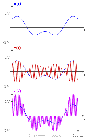
The graph shows the source signal $q(t)$ at the top and the transmission signal $s(t)$ in the middle.
The sink signal $v(t)$ is shown at the bottom (violet waveform).
- This obviously does not match the source signal (blue dashed curve).
- The reason for this undesired result $v(t) ≠ q(t)$ could be a missing or wrongly dimensioned low-pass filter, for example.
In the subtasks (3) and (4) , a so-called trapezoidal low-pass filter is used, whose frequency response is as follows:
- $$H_{\rm E}(f) = \left\{ \begin{array}{l} \hspace{0.25cm}1 \\ \frac{f_2 -|f|}{f_2 -f_1} \\ \hspace{0.25cm} 0 \\ \end{array} \right.\quad \quad \begin{array}{*{10}c} {\rm{f\ddot{u}r}} \\ {\rm{f\ddot{u}r}} \\ {\rm{f\ddot{u}r}} \\ \end{array}\begin{array}{*{20}c} {\hspace{0.94cm}\left| \hspace{0.005cm} f\hspace{0.05cm} \right| < f_1,} \\ {f_1 \le \left| \hspace{0.005cm}f\hspace{0.05cm} \right| \le f_2,} \\ {\hspace{0.94cm}\left|\hspace{0.005cm} f \hspace{0.05cm} \right| > f_2.} \\ \end{array}$$
Hints:
- This exercise belongs to the chapter Synchronous Demodulation.
- Particular reference is made to the page Block diagram and time domain representation.
- In contrast to Exercise 2.4 , $f_1$ and $f_2$ do not describe signal frequencies, but instead relate to the low-pass filter.
Questions
Musterlösung
- Das dargestellte Sinkensignal $v(t)$ stimmt exakt mit dem als Gleichung gegebenen Signal $b(t)$ überein und enthält somit auch Anteile um die doppelte Trägerfrequenz.
- Das Filter $H_{\rm E}(f)$ fehlt entweder ganz oder dessen obere Grenzfrequenz $f_2$ ist zu hoch.
- Bezüglich der unteren Grenzfrequenz $f_1$ ist nur die Aussage möglich, dass diese kleiner ist als die kleinste im Signal $b(t)$ vorkommende Frequenz $\text{(2 kHz)}$.
- Ob ein Gleichanteil durch das Filter entfernt wird oder nicht, ist unklar, da ein solcher im Signal $b(t)$ nicht enthalten ist.
(2) Richtig sind die Aussagen 1 und 3:
- Voraussetzung für eine verzerrungsfreie Demodulation ist, dass bis zu einer bestimmten Frequenz $f_1$ alle Spektralanteile gleich und möglichst ungedämpft übertragen werden und alle Anteile bei Frequenzen $f > f_2$ vollständig unterdrückt werden.
- Der Rechteck– und der Trapeztiefpass erfüllen diese Bedingung.
(3) Sichergestellt werden muss, dass der $\text{5 kHz}$–Anteil noch im Durchlassbereich liegt:
- $$f_{\text{1, min}}\hspace{0.15cm}\underline{ =5 \ \rm kHz}.$$
(4) Alle Spektralanteile in der Umgebung der doppelten Trägerfrequenz – genauer gesagt zwischen $\text{95 kHz}$ und $\text{ 105 kHz}$ – müssen vollständig unterdrückt werden:
- $$f_{\text{2, max}}\hspace{0.15cm}\underline{ =95 \ \rm kHz}.$$
- Ansonsten würde es zu nichtlinearen Verzerrungen kommen.
(5) Richtig ist der Lösungsvorschlag 2:
- Die Grenzfrequenz} $f_{\rm G} = \text{ 4 kHz}$ hätte (lineare) Verzerrungen zur Folge, da dann der $\text{5 kHz}$–Anteil abgeschnitten würde.
- Zu bevorzugen ist der Tiefpass mit der Grenzfrequenz $f_{\rm G} = \text{6 kHz}$, da mit $f_{\rm G} = \text{10 kHz}$ dem Nutzsignal $v(t)$ mehr Rauschanteile überlagert wären.
