Contents
- 1 General remarks
- 2 Ideal low-pass filter – Rectangular-in-frequency
- 3 Slit low-pass filter – Rectangular-in-time
- 4 Gaussian low-pass filter
- 5 Trapezoidal low-pass filter
- 6 Raised-cosine low-pass filter
- 7 Cosine–square low-pass filter
- 8 Derivation of system theoretical high-pass functions
- 9 Exercises for the chapter
General remarks
All low-pass functions described in the next sections have the following properties:
- The frequency response $H(f)$ is real and even so that according to the $\text{Assignment Theorem}$ the associated impulse response $h(t)$ is always real and even, too.
- Thus, it is obvious that the systems considered here are non-causal and hence not realizable. The description of causal systems is given in the chapter »Description of Causal Realizable Systems« of this book.
- The advantage of these »system theoretical filter functions« is the simple description by at most two parameters such that the filter influence can be represented in a transparent way.
- The most important frequency response parameter is the »equivalent bandwidth« according to the definition via the equal-area rectangle:
- $$\Delta f = \frac{1}{H(f=0)}\cdot \int_{-\infty}^{+\infty}H(f) \hspace{0.15cm} {\rm d}f.$$
- According to the so-called »Reciprocity Theorem of time duration and bandwidth« the »equivalent duration of the impulse response« is thus fixed, which is also defined via the equal-area rectangle:
- $$\Delta t = \frac{1}{h(t=0)}\cdot \int_{-\infty}^{+\infty}h(t) \hspace{0.15cm} {\rm d}t = \frac{1}{\Delta f}.$$
- The direct signal $\rm (DC)$ transmission factor is always assumed to be $H(f = 0) = 1$ unless explicitly stated otherwise.
- From every low-pass function corresponding high-pass functions can be derived as shown in the section »Derivation of system theoretical high-pass functions«.
Ideal low-pass filter – Rectangular-in-frequency
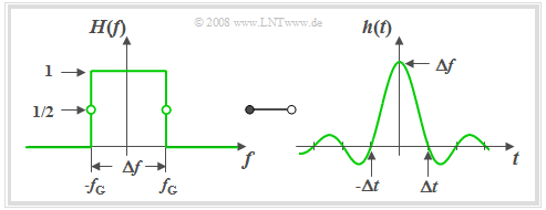
$\text{Definition:}$ An »ideal low-pass filter« is on hand if its frequency response has the following rectangular shape:
- $$H(f) = H_{\rm RLP}(f) =\left\{ \begin{array}{l} \hspace{0.25cm}1 \\ 0.5 \\\hspace{0.25cm} 0 \\ \end{array} \right.\quad \quad\begin{array}{*{10}c} \text {for} \\ \text {for} \\ \text {for} \\ \end{array}\begin{array}{*{20}c}{\vert \hspace{0.005cm}f\hspace{0.05cm} \vert< \Delta f/2,} \\{\vert \hspace{0.005cm}f\hspace{0.05cm} \vert = \Delta f/2,} \\{\vert \hspace{0.005cm}f\hspace{0.05cm} \vert > \Delta f/2.} \\\end{array}$$
- We sometimes also use the term »rectangular low-pass filter« $\rm (RLP)$.
- Here $Δf$ denotes the »system theoretical bandwidth«.
- $f_{\rm G}=Δf/2$ denotes the »cut-off frequency« $($German: "Grenzfrequenz" ⇒ subscript $\rm G)$.
The graph shows such an ideal low-pass filter in the frequency and time domain.
The following can be concluded from these curves:
- Due to the abrupt, infinitely steep roll-off the »3 dB cut-off frequency« ⇒
$f_{\rm G}$ is here exactly half the »system theoretic bandwidth« $Δf$.
- All spectral components with $f \lt f_{\rm G}$ are transmitted undistorted ⇒ »pass band«.
- All components with $f \gt f_{\rm G}$ are completely suppressed ⇒ »stop band«.
- By definition, $H(f) = 0.5$ holds for $f = \pm f_{\rm G}$.
Description of the ideal low-pass filter in the time domain:
- According to the inverse Fourier transform the »impulse response« $($right diagram$)$:
- $$h(t) = h_{\rm RLP}(t) =\Delta f \cdot {\rm si}(\pi \cdot \Delta f \cdot t)\hspace{0.55cm}{\rm{with}}\hspace{0.7cm}{\rm si}(x) ={\sin(x)}/{x},\hspace{0.5cm}{\rm or}$$
- $$h_{\rm RLP}(t) =\Delta f \cdot {\rm sinc}(\Delta f \cdot t)\hspace{0.7cm}{\rm{with}}\hspace{0.7cm}{\rm sinc}(x) ={\sin(\pi x)}/{(\pi x)}.$$
- $h(t)$ extended to infinity on both sides and exhibits equidistant zero-crossings at an interval of $Δt = 1/ Δf$.
- The asymptotic decay is inversely proportional to time $|t|$:
- $$|h(t)| = \frac{\Delta f}{\pi \cdot \Delta f \cdot |t|} \cdot \left |{\rm sin}(\pi \cdot \Delta f\cdot t )\right | \le \frac{1}{\pi \cdot |t|}.$$
- It follows that the impulse response is certainly less than $1‰$ of the impulse maximum only for times $t \gt t_{1‰} = 318 \cdot \Delta t$.
- The step response $\sigma(t)$ is obtained from the impulse response by integration and is:
- $${\sigma}(t) = \int_{ - \infty }^{ t } {h ( \tau )} \hspace{0.1cm}{\rm d}\tau = \frac{1}{2} + \frac{1}{\pi} \cdot {\rm Si}(\pi \cdot\Delta f \cdot t ).$$
- Here, the so-called »integral sine function« is used:
- $${\rm Si}(x) = \int_{ 0 }^{ x } {{\rm si} ( \xi )} \hspace{0.1cm}{\rm d}\xi = x - \frac{x^3}{3 \cdot 3!} + \frac{x^5}{5 \cdot 5!} - \frac{x^7}{7 \cdot 7!}+\text{ ...}$$
- $$\Rightarrow \ {\rm Si}(0) = 0, \hspace{0.3cm}{\rm Si}(\infty) = \frac{\pi}{2}, \hspace{0.3cm}{\rm Si}(-x) = -{\rm Si}(x).$$
Slit low-pass filter – Rectangular-in-time
$\text{Definition:}$ An LTI system is called a »slit low-pass filter« $\rm (SLP)$ if the frequency response has the following form:
- $$H(f) = H_{\rm SLP}(f)= {\rm si}(\pi {f}/{ \Delta f})\hspace{0.7cm}{\rm{where} }\hspace{0.7cm}{\rm si}(x) ={\sin(x)}/{x},\hspace{0.7cm}{\rm or}$$
$$\hspace{2.1cm}H_{\rm SLP}(f)= {\rm sinc}({f}/{ \Delta f})\hspace{0.7cm}{\rm{where} }\hspace{0.7cm}{\rm sinc}(x) ={\sin(\pi x)}/{(\pi x)}.$$
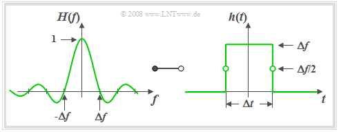
- From the graph on the left it can be seen that the frequency response $H_{\rm SLP}(f)$ of the slit low-pass filter is identical in shape to the impulse response $h_{\rm RLP}(t)$ of the rectangular low-pass filter.
- According to the »Duality Theorem« ⇒ the impulse response $h_{\rm SLP}(t)$ of the slit low-pass filter must also have the same form as the frequency response $H_{\rm RLP}(f)$ of the ideal low-pass filter ⇒ "rectangular-in-time".
- Thus, with the »equivalent duration of the impulse response« $Δt = 1/ Δf$ the following holds:
- $$h(t) = h_{\rm SLP}(t) = \left\{ \begin{array}{l} \hspace{0.25cm}\Delta f \\ \Delta f/2 \\ \hspace{0.25cm} 0 \\ \end{array} \right.\quad \quad \begin{array}{*{10}c} \text{for} \\ \text{for} \\ \text{for} \\ \end{array}\begin{array}{*{20}c} {\vert \hspace{0.005cm}t\hspace{0.05cm} \vert < \Delta t/2,} \\ {\vert \hspace{0.005cm}t\hspace{0.05cm} \vert = \Delta t/2,} \\ {\vert \hspace{0.005cm}t\hspace{0.05cm} \vert > \Delta t/2.} \\ \end{array}$$
Based on the graph on the right the following statements can be derived:
- The slit low-pass filter in this form is also non-causal. However, adding a transit time of $Δt/2$ or more renders the system causal and thus realizable.
- The slit low-pass filter acts as an integrator over the time period $Δt$:
- $$y(t) = x (t) * h (t) = \frac{1}{\Delta t} \cdot \int\limits_{ t - \Delta t/2 }^{ t + \Delta t/2 } {x ( \tau )} \hspace{0.1cm}{\rm d}\tau.$$
- If $x(t)$ is a harmonic oscillation with frequency $f_0 = k \cdot Δf$ $($where $k$ is an integer$)$, then it integrates exactly over $k$ periods and $y(t) = 0$ holds.
- This is also shown by the zeros of $H(f)$.
Gaussian low-pass filter
A filter function frequently used for system-theoretical investigations is the Gaussian low-pass filter, which can also be described by only one parameter, namely the »equivalent bandwidth» $Δf$.
$\text{Definition:}$ For the frequency response and the impulse response of the »Gaussian low-pass filter« $\rm (GLP)$ the following holds:
- $$H(f) = H_{\rm GLP}(f)= {\rm e}^{-\pi(f/\Delta f)^2}\hspace{0.15cm}\bullet\!\!-\!\!\!-\!\!\!-\!\!\circ\, \hspace{0.15cm}h(t) = h_{\rm GLP}(t) = \Delta f \cdot {\rm e}^{-\pi(\Delta f \cdot \hspace{0.03cm} t)^2} .$$
The name goes back to the mathematician, physicist and astronomer $\text{Carl-Friedrich Gauß}$. Gauß did not deal with this subject matter himself, but the mathematical form of the frequency response and impulse response bear a resemblance to the so-called »Gaussian formula« which he discovered for probability theory.
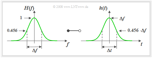
Based on this graph the following statements can be made:
- The »equivalent pulse duration« $Δt$ is also defined via the area-equal rectangle and is equal to the reciprocal of the »equivalent bandwith« $Δf$.
- A narrow-band $($small $Δf)$ filter function $H(f)$ results in a wide $($large $Δt)$ and simultaneously low impulse response $h(t)$.
- The so-called »Reciprocity Theorem« of time duration and bandwidth can be shown particularly clearly in the example of the Gaussian low-pass filter.
- The frequency and time domain representations are in principle of the same form. The Gaussian function is also said to be invariant to Fourier transform.
- The Gaussian low-pass filter is – like the ideal low-pass filter – strongly non-causal and $($exactly$)$ realizable only with infinitely large transit time due to the infinite propagation of its impulse response.
- However, it must be taken into account that $h(t)$ has already decayed to $1‰$ of its maximum value at $t = 1.5 \cdot Δt$. For $t = 3 \cdot Δt$ we even get $h(t) ≈ 5 · 10^{–13} · h(0)$.
- These numerical values show that the Gaussian low-pass filter can be used feasibly for practical simulations as long as runtimes do not play a system-limiting role.
- The »step response« $σ(t)$ is given for the »Gaussian error function« $ϕ(x)$, which is usually given in tabular form in formula collections:
- $$\sigma(t) = \int_{ -\infty }^{ t } {h(\tau)} \hspace{0.1cm}{\rm d}\tau = {\rm \phi}\left( \sqrt{2 \pi }\cdot{t}/{\Delta t} \right) \hspace{0.7cm}{\rm{where}}\hspace{0.7cm}{\rm \phi}(x) = \frac{1}{\sqrt{2 \pi }} \cdot \int_{ -\infty }^{ x } {{\rm e}^{-u^2/2}} \hspace{0.1cm}{\rm d}u.$$
Trapezoidal low-pass filter
The low-pass functions described so far depend on only one parameter – the »equivalent bandwidth« $Δf$. Here, the edge steepness for a given filter type was fixed. Now a low-pass filter with parameterisable edge steepness is described.
$\text{Definition:}$ The frequency response of the »trapezoidal low-pass filter« $\rm (TLP)$ with cut-off frequencies $f_1$ and $f_2 \ge f_1$:
- $$H(f) = H_{\rm TLP}(f)= \left\{ \begin{array}{l} \hspace{0.25cm}1 \\ \frac{f_2 - \vert f \vert }{f_2 -f_1} \\ \hspace{0.25cm} 0 \\ \end{array} \right.\quad \quad \begin{array}{*{10}c} \text{for} \\ \text{for} \\ \text{for} \\ \end{array}\begin{array}{*{20}c} {\hspace{0.94cm}\vert \hspace{0.005cm} f\hspace{0.05cm} \vert < f_1,} \\ {f_1 \le \vert \hspace{0.005cm} f\hspace{0.05cm} \vert \le f_2,} \\ {\hspace{0.94cm}\vert \hspace{0.005cm} f\hspace{0.05cm} \vert > f_2.} \\ \end{array}$$
Instead of $f_1$ and $f_2$ the following parameters can be used to describe $H(f)$:
- the »equivalent bandwidth« determined via the equal-area rectangle:
- $$\Delta f = f_1 + f_2.$$
- the »roll-off factor« $($in frequency domain$)$ as a measure for the edge steepness:
- $$r_{\hspace{-0.05cm}f} = \frac{f_2 - f_1}{f_2 + f_1}.$$
Special cases included in the general representation are:
- the ideal rectangular low-pass filter $(r_{\hspace{-0.05cm}f} = 0)$,
- the triangular low-pass filter $(r_{\hspace{-0.05cm}f} = 1)$.
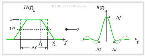
For a roll-off factor of $r_f = 0.5 \ \Rightarrow \ f_2 = 3f_1$ the following graph shows the frequency response $H(f)= H_{\rm TLP}(f)$ on the left and on the right the impulse response
- $$h(t) = h_{\rm TLP}(t) =\Delta f \cdot {\rm sinc}(\Delta f \cdot t )\cdot {\rm sinc}(r_{\hspace{-0.05cm}f} \cdot \Delta f \cdot t )\hspace{0.7cm}{\rm{where}}\hspace{0.7cm}{\rm sinc}(x)= \frac{\sin(\pi x)}{\pi x}.$$
The time-dependent $\rm sinc$–curve of the rectangular low-pass filter with the same equivalent bandwidth is shown dashed for comparison. With the help of the graph and the above equations the following statements can be made:
- The trapezoidal shape is obtained, for example, by convolution of two rectangles of widths $Δf$ and $r_f \cdot Δf$.
- According to the convolution theorem the impulse response is thus the product of two $\rm sinc$–functions with arguments $Δf · t$ and $r_{\hspace{-0.05cm}f} · Δf · t$.
- The first $\rm sinc$–function is part of the $h(t)$ equation for all values of $r_{\hspace{-0.05cm}f}$ and always results in equivalent zero-crossings in the distance $1/Δf$.
- For $0 \lt r_{\hspace{-0.05cm}f} \lt 1$ there are further zero-crossings at multiples of $Δt/r_{\hspace{-0.05cm}f}$.
- The larger $r_{\hspace{-0.05cm}f}$ is $($i.e. for a given $Δf$ with a flatter edge$)$, the faster is the asymptotic decay of the impulse response $h(t)$.
- The fastest possible decay is obtained for the triangular low-pass filter ⇒ $r_{\hspace{-0.05cm}f} = 1$, $f_1 = 0$, $f_2 = Δf$. For this, the following holds in frequency and time domains:
- $$H(f) = \left\{ \begin{array}{c} \hspace{0.25cm} \frac{{\rm \Delta}f -|f|}{{\rm \Delta}f} \\ \hspace{0.25cm} 0 \\ \end{array} \right.\quad \quad \begin{array}{*{10}c} {\rm{for}} \\ {\rm{for}} \\ \end{array}\begin{array}{*{20}c} {\hspace{1cm} \left| \hspace{0.005cm}f\hspace{0.05cm} \right| \le {\rm \Delta}f ,} \\ {\hspace{1cm}\left|\hspace{0.005cm} f \hspace{0.05cm} \right| \ge {\rm \Delta}f } \\ \end{array},$$
- $$h(t) = \Delta f \cdot {\rm sinc}^2( \Delta f \cdot t ),\hspace{0.2cm}{\rm{where}}\hspace{0.4cm}{\rm sinc}(x)= \frac{\sin(\pi x)}{\pi x}.$$
Raised-cosine low-pass filter
Like the »trapezoidal low-pass filter« this low-pass filter is also described by two parameters, which are
- the equivalent bandwidth $Δf$,
- the roll-off factor $r_{\hspace{-0.05cm}f}$.
Its value range lies between $r_{\hspace{-0.05cm}f} = 0$ $($rectangular low-pass filter$)$ and $r_{\hspace{-0.05cm}f} = 1$ $($cosine–squared low-pass filter$)$.
$\text{Definition:}$ With cut-off frequencies $f_1 = Δf · (1 – r_{\hspace{-0.05cm}f})$ and $f_2 = Δf · (1 + r_{\hspace{-0.05cm}f})$ the frequency response of the »raised-cosine low-pass filter« $\rm (RCLP)$:
- $$H(f) = H_{\rm RCLP}(f) =\left\{ \begin{array}{l} \hspace{0.25cm}1 \\ \cos \left( \frac{ \vert f \vert - f_1}{f_2 -f_1}\cdot \pi/2\right) \\ \hspace{0.25cm} 0 \\ \end{array} \right.\quad \quad \begin{array}{*{10}c} \text{for} \\ \text{for} \\ \text{for} \\ \end{array}\begin{array}{*{20}c} {\hspace{0.94cm}\vert \hspace{0.005cm} f\hspace{0.05cm} \vert < f_1,} \\ {f_1 \le \vert \hspace{0.005cm} f\hspace{0.05cm} \vert \le f_2,} \\ {\hspace{0.94cm}\vert \hspace{0.005cm} f\hspace{0.05cm} \vert> f_2.} \\ \end{array}$$
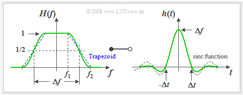
The graph shows $H(f)$ on the left and on the right the impulse response
- $$h(t) = h_{\rm RCLP}(t) =\Delta f \hspace{-0.05cm}\cdot\hspace{-0.05cm} {\rm sinc}( \Delta f \hspace{-0.05cm}\cdot\hspace{-0.05cm} t )\hspace{-0.05cm}\cdot\hspace{-0.05cm} \frac {\cos(\pi \cdot r_{\hspace{-0.05cm}f} \cdot \Delta f \cdot t )}{1 - (2 \cdot r_f \cdot \Delta f \cdot t)^2}.$$
For these graphs the roll-off factor $r_{\hspace{-0.05cm}f} = 0.5$ was used. In other words: $f_2 = 3 \cdot f_1.$
The following is drawn in dashed lines for comparison:
- in the frequency domain the trapezoidal low-pass filter and
- in the time domain the $\rm sinc$ function.
$\text{Please note:}$
- The $\rm sinc$–function is not the inverse Fourier transform of the trapezoidal low-pass filter drawn in blue on the left. It rather describes the ideal rectangular low-pass filter in the time domain, which is not shown in the left graph.
Based on this graph and the above equations the following statements can be made:
- The impulse response $h(t)$ of the raised-cosine low-pass filter has zeros at all multiples of $Δt = 1/Δf$, which are due to the $\rm sinc$–function shown in dashed lines in the right-hand figure.
- The last term in the $h(t)$ equation results in further zeros at multiples of $Δt/r_f$. If $1/r_f$ is an integer as in the above graph $(1/r_f = 2)$, these new zeros coincide with the other zeros and thus are not discernible.
- The larger the roll-off factor $r_f$ and thus the flatter the roll-off is, the more favourable is the transient behaviour of the raised-cosine low-pass filter.
- The raised-cosine low-pass filter usually exhibits a better asymptotic transient behaviour than the trapezoidal low-pass filter with same $r_f$ although the latter has a flatter edge at least at frequency $Δf/2$.
- This suggests that the transient behaviour is not only affected by points of discontinuity $($as in the case of the rectangle$)$ but also by kink points as in the case of the trapezoidal low-pass filter.
Cosine–square low-pass filter
$\text{Definition:}$ For $f_1 = 0$, $f_2 = Δf$ ⇒ $r_f = 1$ the »cosine–square low-pass filter« $\rm (CSLP)$ is obtained as a special case. Its impulse response can also be represented as follows:
- $$H(f) = H_{\rm CSLP}(f)= \cos^2\Big(\frac{\vert f \vert \hspace{0.05cm}\cdot\hspace{0.05cm} \pi}{2\hspace{0.05cm}\cdot\hspace{0.05cm} \Delta f}\Big). $$
Outside this inner frequency range, $H_{\rm CSLP}(f)=0$.
For the impulse response one obtains according to the inverse Fourier transform after some transformations:
- $$h(t)=h_{\rm CSLP}(t)= \Delta f \cdot {\rm sinc}(\Delta f \cdot t)\cdot \big [{\rm sinc}(\Delta f\cdot t +0.5)+{\rm sinc}(\Delta f\cdot t -0.5)\big ],$$
- $$T=1/\Delta f \hspace{0.5cm}\Rightarrow \hspace{0.5cm} h(t)=1/T \cdot {\rm sinc}(t/T)\cdot \big [{\rm sinc}(t/T +0.5)+{\rm sinc}(t/T -0.5)\big ].$$
- Because of the first ${\rm sinc}$–function, $h(t)=0$ for multiples of $T=1/\Delta f$ ⇒ the equidistant zero-crossings of the cosine–rolloff lowpass are preserved.
- Because of the bracket expression, $h(t)$ now exhibits further zero-crossings at $t=\pm1.5 T$, $\pm2.5 T$, $\pm3.5 T$, ... but not at $t=\pm0.5 T$.
- For $t=\pm0.5 T$ the impulse response has the value $\Delta f/2$.
- The asymptotic decay of $h(t)$ in this special case runs with $1/t^3$.
$\text{Furthermore, it should be mentioned}$ that the »cosine-square low-pass filter« is the only low-pass filter that fulfils both »Nyquist criteria«. Here the »eye« in digital transmission is maximally open both vertically and horizontally ⇒ see »Definition and statements of the eye diagram«.
Derivation of system theoretical high-pass functions
So far, six commonly used system theoretic low-pass functions have been considered. For each individual low-pass function there is also an equivalent high-pass function.
$\text{Definition:}$ If $H_{\rm TP}(f)$ is a system–theoretical low-pass function $($German "Tiefpass" ⇒ $\text{TP)}$ with $H_{\rm TP}(f = 0) = 1$, then the »equivalent high-pass function«:
- $$H_{\rm HP}(f) = 1 - H_{\rm TP}(f).$$
Thus, the descriptive quantities in the time domain are:
- $$h_{\rm HP}(t) = \delta (t) - h_{\rm TP}(t),$$
- $$\sigma_{\rm HP}(t) = \gamma (t) - \sigma_{\rm TP}(t). $$
Here, the following denotations are used:
- $h_{\rm HP}(t)$ and $h_{\rm TP}(t)$ denote the impulse responses of the high- and low-pass filter,
- $σ_{\rm HP}(t)$ and $σ_{\rm TP}(t)$ denote the respective step responses,
- $γ(t)$ denotes the jump function as a result of integration over the Dirac delta function $δ(t)$.
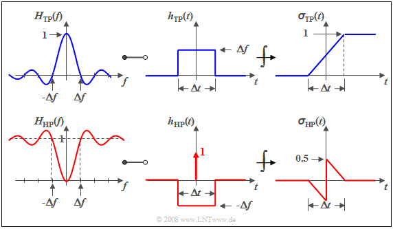
$\text{Example 1:}$ We consider the »slit low-pass filter« ⇒ »rectangular-in-time» which is characterized by
- a $\rm sinc$–shaped frequency response with $H_{\rm TP}(f = 0) = 1$,
- a rectangular impulse response, and
- a linearly increasing step response.
These are shown in the upper diagram.
The sketch below shows the corresponding high-pass functions.
It can be seen that
- $H_{\rm HP}(f = 0) = 0$ because $H_{\rm TP}(f = 0) = 1$,
- consequently the integral over $h_{\rm HP}(t)$ must also be zero, and
- the step response $σ_{\rm HP}(t)$ tends towards the final value
- $$σ_{\rm HP}(t \to \infty)=0.$$
Exercises for the chapter
Exercise 1.5: Rectangular-in-Frequency Low-Pass Filter
Exercise 1.5Z: Sinc-shaped Impulse Response
Exercise 1.6: Rectangular-in-Time Low-Pass Filter
Exercise 1.6Z: Interpretation of the Frequency Response
Exercise 1.7: Nearly Causal Gaussian Low-Pass Filter
Exercise 1.7Z: Overall Systems Analysis
Exercise 1.8: Variable Edge Steepness
Exercise 1.8Z: Cosine-Square Low-Pass Filter
