Difference between revisions of "Aufgaben:Exercise 2.7Z: DSB-AM and Envelope Demodulator"
m |
|||
| Line 3: | Line 3: | ||
}} | }} | ||
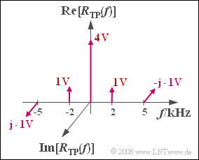
| − | [[File:P_ID1034__Mod_Z_2_7.png|right|frame| | + | [[File:P_ID1034__Mod_Z_2_7.png|right|frame|Spectrum $R_{\rm TP}(f)$ of the received signal in the equivalent low-pass range]] |
| − | + | Assume a source signal | |
:$$ q(t) = 2 \,{\rm V} \cdot \cos(2 \pi \cdot 2\,{\rm kHz} \cdot t ) + 2 \,{\rm V} \cdot \sin(2 \pi \cdot 5\,{\rm kHz} \cdot t )\hspace{0.05cm}.$$ | :$$ q(t) = 2 \,{\rm V} \cdot \cos(2 \pi \cdot 2\,{\rm kHz} \cdot t ) + 2 \,{\rm V} \cdot \sin(2 \pi \cdot 5\,{\rm kHz} \cdot t )\hspace{0.05cm}.$$ | ||
| − | + | This is modulated according to the modulation method "DSB-AM with carrier" and transmitted through an ideal channel. The influence of noise can be disregarded. | |
| − | + | The graph shows the spectrum $R_{\rm TP}(f)$ of the received signal in the equivalent low-pass region, which is composed of Dirac lines at $f = 0$ (originating from the carrier), at $±2\ \rm kHz$ (originating from the cosine component) and at $±5\ \rm kHz$ (originating from the sine component) . | |
| − | * | + | *The locus curve is the plot of the equivalent low-pass signal $r_{\rm TP}(t)$ in the complex plane, |
| − | * | + | * where $r_{\rm TP}(t)$ is the Fourier retransform of $R_{\ \rm TP}(f)$ . |
| Line 23: | Line 23: | ||
| − | '' | + | ''Hints:'' |
| − | * | + | *This exercise belongs to the chapter [[Modulation_Methods/Envelope_Demodulation|Envelope Demodulation]]. |
| − | * | + | *Particular reference is made to the page [[Modulation_Methods/Envelope_Demodulation#Description_using_the_equivalent_low-pass_signal|Description using the equivalent low-pass signal]]. |
| − | === | + | ===Questions=== |
<quiz display=simple> | <quiz display=simple> | ||
| − | { | + | {Estimate the maximum magnitude $q_{\rm max} = {\rm Max} |q(t)|$ of the source signal S. |
|type="{}"} | |type="{}"} | ||
$q_{\rm max} \ = \ $ { 4 3% } $\ \rm V$ | $q_{\rm max} \ = \ $ { 4 3% } $\ \rm V$ | ||
Revision as of 19:30, 20 December 2021
Assume a source signal
- $$ q(t) = 2 \,{\rm V} \cdot \cos(2 \pi \cdot 2\,{\rm kHz} \cdot t ) + 2 \,{\rm V} \cdot \sin(2 \pi \cdot 5\,{\rm kHz} \cdot t )\hspace{0.05cm}.$$
This is modulated according to the modulation method "DSB-AM with carrier" and transmitted through an ideal channel. The influence of noise can be disregarded.
The graph shows the spectrum $R_{\rm TP}(f)$ of the received signal in the equivalent low-pass region, which is composed of Dirac lines at $f = 0$ (originating from the carrier), at $±2\ \rm kHz$ (originating from the cosine component) and at $±5\ \rm kHz$ (originating from the sine component) .
- The locus curve is the plot of the equivalent low-pass signal $r_{\rm TP}(t)$ in the complex plane,
- where $r_{\rm TP}(t)$ is the Fourier retransform of $R_{\ \rm TP}(f)$ .
Hints:
- This exercise belongs to the chapter Envelope Demodulation.
- Particular reference is made to the page Description using the equivalent low-pass signal.
Questions
Musterlösung
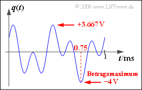
(1) Die Grafik zeigt, dass das Quellensignal alle Werte zwischen $–4 \ \rm V$ und $+3.667\ \rm V$ annehmen kann.
- Der maximale Betrag tritt zum Beispiel zum Zeitpunkt $t = t_0 =0.75\ \rm ms$ auf:
- $$q(t = t_0) = 2 \,{\rm V} \cdot \cos(2 \pi \cdot 2\,{\rm kHz} \cdot t_0 ) + 2 \,{\rm V} \cdot \sin(2 \pi \cdot 5\,{\rm kHz} \cdot t_0 )$$
- $$\Rightarrow \hspace{0.3cm}q(t = 0.75 \,{\rm ms}) = 2 \,{\rm V} \cdot \cos(3 \pi) + 2 \,{\rm V} \cdot \sin(7.5 \pi)= -4 \,{\rm V}\hspace{0.05cm}.$$
- Daraus folgt für den maximalen Betrag: $q_{\rm max}\hspace{0.15cm}\underline{ = 4 \ \rm V}$.
(2) In der Angabenseite–Grafik gibt das Gewicht der Diraclinie bei $f = 0$ die Amplitude des zugesetzten Trägers an.
- Diese ist $A_{\rm T}\hspace{0.15cm}\underline{ = 4\ \rm V }$.
- Daraus erhält man den Modulationsgrad $m = q_{\rm max}/A_{\rm T} \hspace{0.15cm}\underline{ = 1}$.
(3) Richtig sind die Lösungsvorschläge 2 und 3:
- Da der Modulationsgrad nicht größer als $m = 1$ ist, führt auch der Hüllkurvendemodulator nicht zu Verzerrungen.
- Der wesentliche Vorteil der Hüllkurvendemodulation ist, dass keine Frequenz– und Phasensynchronität notwendig ist.
- Nachteilig ist, dass im Gegensatz zur Synchrondemodulation beim Sender eine deutlich höhere Leistung aufgebracht werden muss.
- Bei $m = 1$ ergibt sich gegenüber der ZSB–AM ohne Träger die dreifache Sendeleistung.
(4) Richtig sind die Lösungsvorschläge 1 und 3:
- Mit $ω_2 = 2 π · 2 \ \rm kHz$ und $ω_5 = 2 π · \ \rm 5 kHz$ gilt:
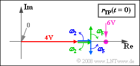
- $$ r_{\rm TP}(t) = 4 \,{\rm V} \hspace{-0.05cm}+\hspace{-0.05cm} 1 \,{\rm V} \cdot {\rm e}^{{\rm j} \cdot \hspace{0.03cm}\omega_{\rm 2}\cdot \hspace{0.03cm}t} \hspace{-0.05cm}+\hspace{-0.05cm} 1 \,{\rm V} \cdot {\rm e}^{-{\rm j} \cdot \hspace{0.03cm}\omega_{\rm 2}\cdot \hspace{0.03cm}t} \hspace{-0.05cm}-\hspace{-0.05cm} \hspace{0.15cm}{\rm j} \cdot1 \,{\rm V} \cdot {\rm e}^{{\rm j} \cdot \hspace{0.03cm}\omega_{\rm 5}\cdot \hspace{0.03cm}t} \hspace{-0.05cm}+\hspace{-0.05cm} {\rm j} \cdot1 \,{\rm V} \cdot {\rm e}^{-{\rm j} \cdot \hspace{0.03cm}\omega_{\rm 5}\cdot \hspace{0.03cm}t} \hspace{0.05cm}. \hspace{0.1cm}$$
- Bei der Konstruktion der Ortskurve $r_{TP}(t)$ sind somit genau fünf Zeiger zu berücksichtigen ⇒ Antwort 1 ist richtig. Die Grafik zeigt eine Momentaufnahme zum Zeitpunkt $t = 0$.
- Der (rote) Träger ist für alle Zeiten durch den reellen Zeiger der Länge $4 \ \rm V$ gegeben. Im Gegensatz zum Zeigerdiagramm (Darstellung des analytischen Signals) dreht dieser nicht ⇒ Antwort 2 ist falsch.
- Die dritte Aussage ist ebenso wie die Aussage 1 richtig: Die Drehzeiger bei negativen Frequenzen drehen in mathematisch negativer Richtung (im Uhrzeigersinn) im Gegensatz zu den beiden Zeigern mit $f > 0$.
- Die letzte Aussage trifft nicht zu. Je größer die Frequenz $f$ ist, um so schneller dreht der zugehörige Zeiger.
(5) Richtig sind die Aussagen 1 und 2:
- Im betrachteten Beispiel kann für das äquivalente TP–Signal auch geschrieben werden:
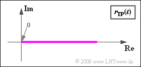
- $$r_{\rm TP}(t) = q(t) + A_{\rm T} \hspace{0.05cm}.$$
- Damit ist offensichtlich, dass $r_{\rm TP}(t)$ stets reell ist. Aus den Teilaufgaben (1) und (2) folgt zudem $r_{\rm TP}(t) ≥ 0$.
Das bedeutet:
- Die Ortskurve ist hier eine horizontale Gerade auf der reellen Gerade und liegt stets in der rechten Halbebene.
- Dies sind die beiden notwendigen Bedingungen, dass mit einem Hüllkurvendemodulator das Nachrichtensignal verzerrungsfrei wiedergewonnen werden kann.
- Ist eine dieser Voraussetzungen nicht erfüllt, so kommt es zu nichtlinearen Verzerrungen, nicht zu linearen ⇒ Antwort 3 ist falsch.


