Difference between revisions of "Aufgaben:Exercise 3.1Z: Frequency Response of the Coaxial Cable"
m (Guenter moved page Aufgabe 3.1Z: Frequenzgang des Koaxialkabels to Exercise 3.1Z: Frequency Response of the Coaxial Cable) |
|
(No difference)
| |
Revision as of 15:46, 7 May 2022
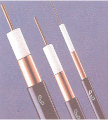
A so-called standard coaxial cable with core diameter $2.6 \ \rm mm$, outer diameter $9.5 \ \rm mm$ and length $l$ has the following frequency response:
- $$H_{\rm K}(f) \ = \ {\rm e}^{- \alpha_0 \hspace{0.05cm} \cdot \hspace{0.05cm} l} \cdot {\rm e}^{- \alpha_1 \hspace{0.05cm}\cdot \hspace{0.05cm}l \hspace{0.05cm}\cdot \hspace{0.05cm}f} \cdot {\rm e}^{- \alpha_2 \hspace{0.05cm}\cdot \hspace{0.05cm}l\hspace{0.05cm}\hspace{0.05cm}\cdot \sqrt{f}} \cdot {\rm e}^{- {\rm j} \hspace{0.05cm}\cdot \hspace{0.05cm} \beta_1 \hspace{0.05cm}\cdot \hspace{0.05cm} l \hspace{0.05cm}\cdot \hspace{0.05cm}f} \cdot {\rm e}^{- {\rm j} \hspace{0.05cm}\cdot \hspace{0.05cm} \beta_2 \hspace{0.05cm}\cdot \hspace{0.05cm}l\hspace{0.05cm}\hspace{0.05cm}\cdot \sqrt{f}} \hspace{0.05cm}.$$
The attenuation parameters $\alpha_0$, $\alpha_1$ and $\alpha_2$ are to be entered in Neper $(\rm Np)$, the phase parameters $\beta_1$ and $\beta_2$ in Radian $(\rm rad)$. The following numerical values apply:
- $$\alpha_0 = 0.00162 \hspace{0.15cm}\frac{\rm Np}{\rm km} \hspace{0.05cm},\hspace{0.2cm} \alpha_1 = 0.000435 \hspace{0.15cm}\frac{\rm Np}{\rm km\cdot{\rm MHz}} \hspace{0.05cm}, \hspace{0.2cm} \alpha_2 = 0.2722 \hspace{0.15cm}\frac{\rm Np}{\rm km\cdot\sqrt{\rm MHz}} \hspace{0.05cm}.$$
Often, to describe a linear time-invariant system (LZI) in terms of system theory, one uses
- the attenuation function $($in $\rm Np$ or $\rm dB)$:
- $$a_{\rm K}(f) = - {\rm ln} \hspace{0.10cm}|H_{\rm K}(f)|= - 20 \cdot {\rm lg} \hspace{0.10cm}|H_{\rm K}(f)| \hspace{0.05cm},$$
- the phase function $($in $\rm rad$ or $\rm degrees)$:
- $$b_{\rm K}(f) = - {\rm arc} \hspace{0.10cm}H_{\rm K}(f) \hspace{0.05cm}.$$
In practice one often uses the approximation
- $$H_{\rm K}(f) = {\rm e}^{- \alpha_2 \hspace{0.05cm}\cdot \hspace{0.05cm}l\hspace{0.05cm}\hspace{0.05cm}\cdot \sqrt{f}} \cdot {\rm e}^{- {\rm j} \hspace{0.05cm}\cdot \hspace{0.05cm} \beta_2 \hspace{0.05cm}\cdot \hspace{0.05cm}l\hspace{0.05cm}\hspace{0.05cm}\cdot \sqrt{f}}\hspace{0.3cm}\Rightarrow \hspace{0.3cm} a_{\rm K}(f) = \alpha_2 \cdot l \cdot \sqrt{f}, \hspace{0.2cm}b_{\rm K}(f) = a_{\rm K}(f) \cdot \frac{\rm rad}{\rm Np}\hspace{0.05cm}.$$
This is allowed because $\alpha_2$ and $\beta_2$ have exactly the same numerical value – just different pseudo units. Using the definition of the characteristic cable attenuation (in Neper or decibels)
- $$a_{\rm * (Np)} = a_{\rm K}(f = {R_{\rm B}}/{2}) = 0.1151 \cdot a_{\rm * (dB)}$$
digital systems with different bit rate $R_{\rm B}$ and cable length $l$ can be treated uniformly.
Notes:
- The exercise belongs to the chapter Causes and Effects of Intersymbol Interference.
- Reference is made in particular to the section Signals, Basis Functions and Vector Spaces.
Questions
Solution
- The $\alpha_0$–term causes only frequency-independent attenuation and the $\beta_1$–term (linear phase) causes frequency-independent delay.
- All other terms contribute to the (linear) distortions.
(2) With $a_0 = \alpha_0 \cdot l$, the following equation must be satisfied:
- $${\rm e}^{- a_0 } \ge 0.99 \hspace{0.3cm} \Rightarrow \hspace{0.3cm}a_0 < {\rm ln} \hspace{0.10cm}\frac{1}{0.99}\approx 0.01\,\,{\rm (Np)} \hspace{0.05cm}.$$
This gives the following for the maximum cable length
- $$l_{\rm max} = \frac{a_0 }{\alpha_0 } = \frac{0.01\,\,{\rm Np}}{0.00162\,\,{\rm Np/km}}\hspace{0.15cm}\underline {\approx 6.173\,\,{\rm km}} \hspace{0.05cm}.$$
(3) For the attenuation curve, considering all terms:
- $$a_{\rm K}(f) \ = \ \big[\alpha_0 + \alpha_1 \cdot f + \alpha_2 \cdot \sqrt{f}\hspace{0.05cm}\big] \cdot l = \big [0.00162 + 0.000435 \cdot 70 + 0.2722 \cdot \sqrt{70}\hspace{0.05cm}\big]\, \frac{\rm Np}{\rm km} \cdot 2\,{\rm km} = \hspace{0.15cm}\underline {= 4.619\, {\rm Np}}\hspace{0.05cm}.$$
(4) According to the calculation at point (3), the attenuation value $\underline {4.555\,{\rm Np}}$ is obtained here.
(5) For any positive quantity $x$ holds:
- $$x_{\rm Np} = {\rm ln} \hspace{0.10cm} x = \frac{{\rm lg} \hspace{0.10cm} x}{{\rm lg} \hspace{0.10cm} {\rm e}} = \frac{1}{{20 \cdot \rm lg} \hspace{0.10cm} {\rm e}} \cdot (20 \cdot {\rm lg} \hspace{0.10cm} x) = 0.1151 \cdot x_{\rm dB}\hspace{0.3cm} \Rightarrow \hspace{0.3cm} x_{\rm dB} = 8.686 \cdot x_{\rm Np}\hspace{0.05cm}.$$
Thus, the attenuation value $4.555\,{\rm Np}$ is identical to $\underline{39.57\,{\rm dB} }$.
(6) Solutions 1, 4 and 5 are correct:
- With the restriction to the attenuation term with $\alpha_2$, the following holds for the frequency response:
- $$H_{\rm K}(f) = {\rm e}^{- \alpha_2 \hspace{0.05cm}\cdot \hspace{0.05cm}l\hspace{0.05cm}\hspace{0.05cm}\cdot \sqrt{f}} \cdot {\rm e}^{- {\rm j} \hspace{0.05cm}\cdot \hspace{0.05cm} \beta_1 \hspace{0.05cm}\cdot \hspace{0.05cm} l \hspace{0.05cm}\cdot f} \cdot {\rm e}^{- {\rm j} \hspace{0.05cm}\cdot \hspace{0.05cm} \beta_2 \hspace{0.05cm}\cdot \hspace{0.05cm}l\hspace{0.05cm}\hspace{0.05cm}\cdot \sqrt{f}} \hspace{0.05cm}.$$
- If we omit the $\beta_1$ phase term, nothing changes with respect to the distortions. Only the phase and group delay would become smaller (both equal) by the value $\tau_1 = (\beta_1 \cdot l)/2\pi$.
- On the other hand, if the $\beta_2$–term is omitted, completely different ratios result:
- The frequency response $H_{\rm K}(f)$ now no longer satisfies the requirement of a causal system; for such a system $H_{\rm K}(f)$ must be minimum-phase.
- The impulse response $h_{\rm K}(t)$ is symmetrical about $t = 0$ with real frequency response, which does not correspond to the conditions.
- Therefore as an approximation for the coaxial cable frequency response is allowed:
- $$a_{\rm K}(f) = \alpha_2 \cdot l \cdot \sqrt{f}, \hspace{0.2cm}b_{\rm K}(f) = a_{\rm K}(f) \cdot \frac{\rm rad}{\rm Np}\hspace{0.05cm}.$$
- That means: $a_{\rm K}(f)$ and $b_{\rm K}(f)$ of a coaxial cable are identical in form and differ only in their units.
- For a digital system with bit rate $R_{\rm B} = 140\,{\rm Mbit/s}$ ⇒ $R_{\rm B}/2 = 70\,{\rm Mbit/s}$ and cable length $l = 2\,{\rm km}$, $a_* ≈ 40\,{\rm dB}$ is indeed valid – see solution to (5).
- A system with four times the bit rate ($R_{\rm B}/2 = 280\,{\rm Mbit/s}$) and half the length ($l = 1\,{\rm km}$) results in the same characteristic cable attenuation.
- In contrast, for a system with $R_{\rm B}/2 = 35\,{\rm Mbit/s}$ and $l = 2\,{\rm km}$ to
- $$a_{\rm dB} = 0.2722 \frac{\rm Np}{\rm km\cdot \sqrt{\rm MHz}} \cdot 2 \ \rm km \cdot \sqrt{35 \ \rm MHz} \cdot 8.6859 \frac{\rm dB}{\rm Np} ≈ 28 \ \rm dB.$$
